1.2
1.3
LIFTING AND SHIPPING
To lift a crated V-18APC II bandsaw, a forklift can be used. Minimum capacity of 7500 LB. at 48” from the mast
is required as well as 6’ forks.
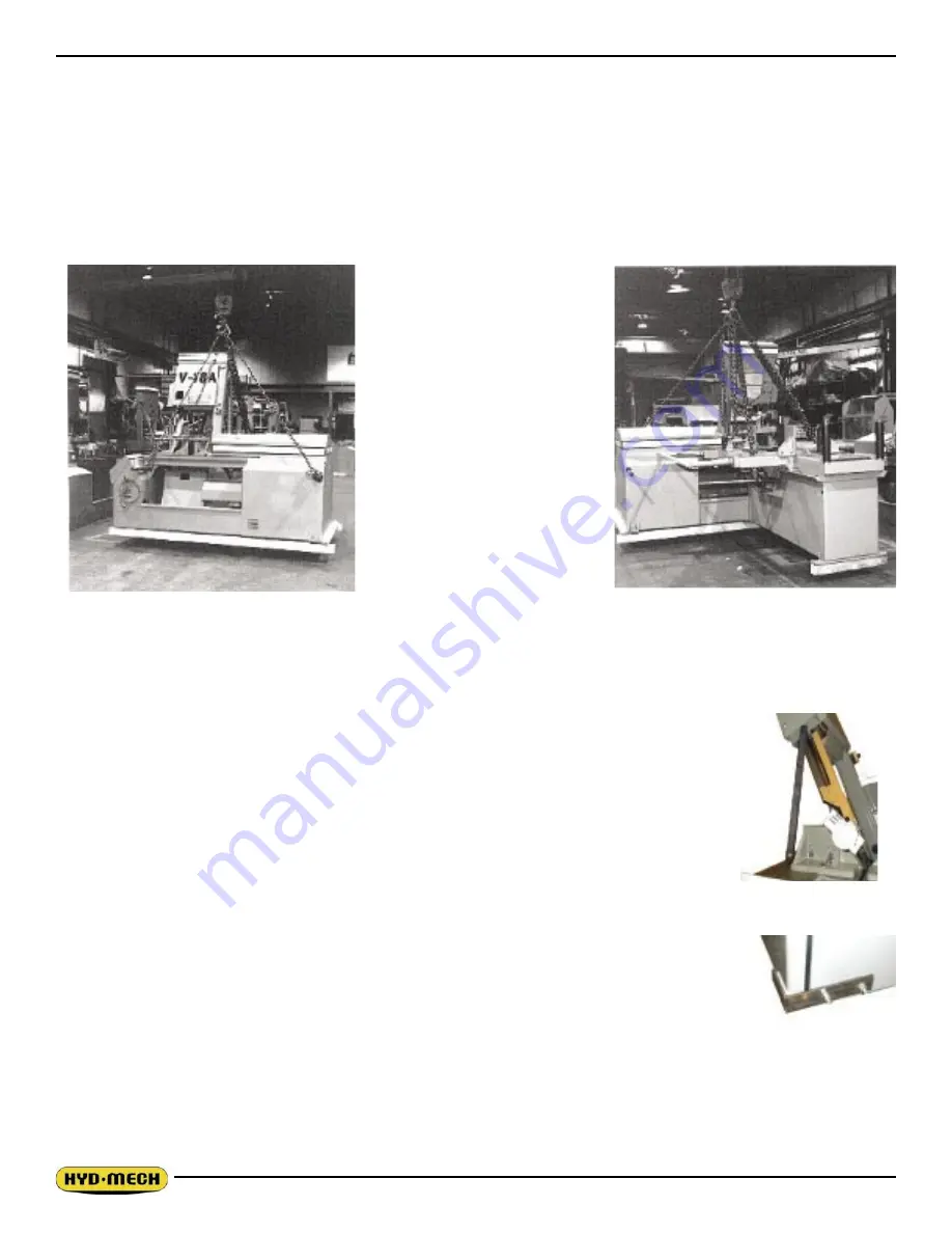
To lift the bandsaw with a crane, position the head to 65°. Then insert 2” diameter shafts through the lifting
holes in the machine base.
An experienced rigger should select the rigging based on the 7500 LB. weight of the saw. The photos below
show preferred rigging.
WARNING: Under no circumstances should the lifting chains be pushing against the head.
REMOVING HEAD RESTRAINTS
Before start-up, remove the head support strut installed for shipping purposes to secure
the head to the base. Replace the two 5/16 NC countersunk screws which fasten the
wear-strip down.
HYDRAULIC DOOR RESTRAINT
There is a restraint bolted to the hydraulic cabinet to keep the door in place during
shipping which must be removed while the machine is raised off the floor. The two bolt
heads can be reached from underneath the cabinet. When the hydraulic door is open,
check for hydraulic leaks that may have developed during shipping.
INSTALLATION OF THE CONTROL PANEL
The V18APC II comes equipped an articulating control panel. This panel is normally
removed and placed on the saw table for shipping purposes. The control panel MUST BE
REINSATLLED PRIOR TO MACHINE STARTUP. Take lifting precautions when installing
the panel as it weights 150 LB.
To re-install the panel, follow these steps:
1. Remove all of the packing material.
2. Remove the base front cover from the machine to gain access to the interior of the base.
3. Lift the panel and move it into position as shown below. Insert the extra length of hoses and conduit
back into the front of the saw base enclosure.
Summary of Contents for V-18 APC
Page 2: ......
Page 6: ......
Page 12: ......
Page 28: ......
Page 48: ...4 6 V18 APC 208 240 VOLT ELECTRICAL SCHEMATIC NO OPTIONS ...
Page 49: ...4 7 ...
Page 50: ...4 8 ...
Page 51: ...4 9 ...
Page 52: ...4 10 V18 APC 208 240 VOLT WIRING DIAGRAM NO OPTIONS ...
Page 53: ...4 11 ...
Page 54: ...4 12 ...
Page 55: ...4 13 ...
Page 56: ...4 14 V18 APC 208 240 VOLT INPUT AND OUTPUTS NO OPTIONS ...
Page 57: ...4 15 ...
Page 58: ...4 16 ...
Page 59: ...4 17 ...
Page 60: ...4 18 V18 APC 208 240 VOLT ELECTRICAL SCHEMATIC ...
Page 61: ...4 19 ...
Page 62: ...4 20 ...
Page 63: ...4 21 ...
Page 64: ...4 22 V18 APC 208 240 VOLT WIRING DIAGRAM ...
Page 65: ...4 23 ...
Page 66: ...4 24 ...
Page 67: ...4 25 ...
Page 68: ...4 26 V18 APC 208 240 VOLT INPUT AND OUTPUTS ...
Page 69: ...4 27 ...
Page 70: ...4 28 ...
Page 71: ...4 29 ...
Page 72: ...4 30 V18 APC 480 575 VOLT ELECTRICAL SCHEMATIC NO OPTIONS ...
Page 73: ...4 31 ...
Page 74: ...4 32 ...
Page 75: ...4 33 ...
Page 76: ...4 34 V18 APC 480 575 VOLT ELECTRICAL WIRING DIAGRAM NO OPTIONS ...
Page 77: ...4 35 ...
Page 78: ...4 36 ...
Page 79: ...4 37 ...
Page 80: ...4 38 V18 APC 480 575 VOLT INPUT AND OUTPUT DEVICES NO OPTIONS ...
Page 81: ...4 39 ...
Page 82: ...4 40 ...
Page 83: ...4 41 ...
Page 84: ...4 42 V18 APC 480 575 VOLT ELECTRICAL SCHEMATIC ...
Page 85: ...4 43 ...
Page 86: ...4 44 ...
Page 87: ...4 45 ...
Page 88: ...4 46 V18 APC 480 575 VOLT ELECTRICAL WIRING DIAGRAM ...
Page 89: ...4 47 ...
Page 90: ...4 48 ...
Page 91: ...4 49 ...
Page 92: ...4 50 V18 APC 480 575 VOLT INPUT AND OUTPUT DEVICES ...
Page 93: ...4 51 ...
Page 94: ...4 52 ...
Page 97: ...5 3 V18 APC HYDRAULIC SCHEMATIC ...
Page 98: ...5 4 V18 APC PLUMBING DIAGRAM ...
Page 100: ...6 2 GUIDE ARM ASSEMBLY ...
Page 110: ...6 12 SQUARING VISE ASSEMBLY ...
Page 112: ...6 14 SHUTTLE VISE ASSEMBLY ...
Page 115: ...6 17 COOLANT ASSEMBLY ...
Page 118: ...6 20 CHIP CONVEYOR SHOWN WITH CRANK AND OPTIONAL HYDRAULIC MOTOR ...
Page 124: ...7 4 GUIDE ARM ASSEMBLY FOR EXTENDED HEAD OPTION ...
Page 128: ......
Page 130: ...8 2 ...
Page 131: ...8 3 ...
Page 132: ......


