16
EDS
3000
IO-Link
Edition: 20.04.2020
HYDAC
ELECTRONIC
GMBH
Part no.: 669897
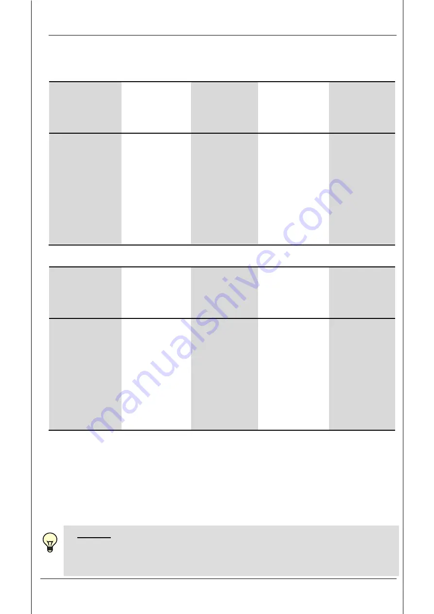
11.2 Setting ranges for the switching outputs
Measurement
range
Lower limit of
RP / FL
Upper limit of
SP / FH
Minimum
difference betw.
RP and SP
or FL and FH
Increment*
in bar
in bar
in bar
in bar
- 1 .. 1
-0.98
1.00 0.02 0.01
0 .. 1
0.010
1.000 0.010 0.002
0 .. 2.5
0.025
2.500 0.025 0.005
0 .. 6
0.06
6.00 0.06 0.01
0 .. 10
0.10
10.00 0.10 0.02
0 .. 16
0.20
16.00 0.20 0.05
0 .. 40
0.4
40.0 0.4 0.1
0 .. 100
1.0
100.0 1.0
0.2
0 .. 250
2.5
250.0 2.5
0.5
0 .. 400
4
400 4
1
0 .. 600
6
600 6
1
* All ranges shown in the table can be adjusted by the increments shown.
Measurement
range
Lower limit of
RP / FL
Upper limit of
SP / FH
Minimum
difference betw.
RP and SP
or FL and FH
Increment*
in psi
in psi
in psi
in psi
0 .. 15
0.15
15 0.15 0.05
0 .. 30
0.30
30 0.3 0.05
0 .. 50
0.5
50 0.5 0.1
-14 .. 75
-13.0
75 1.0 0.2
0 .. 150
1.5
150 1.5 0.5
0 .. 250
2.5
250 2.5 0.5
0 .. 500
5
500 5
1
0 .. 1000
10
1000 10
2
0 .. 3000
30
3000 30
5
0 .. 6000
60
6000 60
10
0 .. 9000
90
9000 90
20
* All ranges shown in the table can be adjusted by the increments shown.
SP = switch point
RP = switch-back point
FL = pressure window lower value
FH = pressure window upper value
11.3 Analogue output
The universal output "ou2" can be set to 4 .. 20 mA or 0 .. 10 V (corresponds to
measuring range).
NOTICE
If the sensor is operated in conjunction with an IO-Link master and if pin 2 is
used as an analogue output, pin 2 may not be connected with the IO-Link
master, as it does not support analogue signals.


