background image

 
24 


ETS 3000 IO-Link 


Stand: 18.08.2016

 HYDAC 

ELECTRONIC 

GMBH


Mat. Nr.: 669904 


17 Zubehör   

17.1  FÜR DEN ELEKTRISCHEN ANSCHLUSS 


ZBE 06 (4-pol.) 

Kupplungsdose M12x1, 
abgewinkelt 
Kabeldurchmesser:  
2,5 .. 6,5 mm 
Material-Nr.: 6006788 


ZBE 06-02 (4-pol.)  

Kupplungsdose M12x1, 
abgewinkelt mit 2m Leitung, 
Material-Nr.: 6006790 
 

ZBE 06-05 (4-pol.),  

Kupplungsdose M12x1, 
abgewinkelt mit 5m Leitung 
Material-Nr.: 6006789 


Farbkennung: Pin 

1:  braun 


Pin 

2: 

weiß 


Pin 

3: 

blau 


Pin 

4: 

schwarz 

17.2  FÜR DEN MECHANISCHEN ANSCHLUSS 

ZBM 3000 

Schelle zur Wandbefestigung, anschraubbar  
(Werkstoff Unterteil: TPE Santoprene 10187; Oberteil: Bandstahl DIN 95381-1.4571) 
Material-Nr.: 3184630


Summary of Contents for ETS 3000

Page 1: ...riginal instructions Notice d utilisation traduction de l original Elektronischer Temperaturschalter Electronic Temperature Switch Thermocontacteur électronique ETS 3000 Mit IO Link Schnittstelle With IO Link Interface Avec interface IO Link Mat Nr 669904 Stand 18 08 2016 D E F ...

Page 2: ...ellungen 13 10 1 HAUPTMENÜ 13 10 2 ERWEITERTE FUNKTIONEN 14 10 3 ÄNDERN DER GRUNDEINSTELLUNGEN 15 11 Rücksetzen der Spitzenwerte 16 12 Programmierfreigabe 16 12 1 ÄNDERN DER PROGRAMMIERFREIGABE 16 13 Fehlermeldungen 16 14 Anschlussbelegung 17 15 Technische Daten 18 15 1 ETS 3200 mit integriertem Sensor 18 15 2 ETS 3800 für externen Sensor 20 16 Bestellangaben 22 16 1 ETS 3200 mit integriertem Sens...

Page 3: ...bar sein Bitte beachten Sie dass die in dieser Dokumentation gemachten Angaben der Gerätetechnik zu dem Zeitpunkt der Literaturerstellung entsprechen Abweichungen bei technischen Angaben Abbildungen und Maßen sind deshalb möglich Entdecken Sie beim Lesen dieser Dokumentation Fehler oder haben weitere Anregungen und Hinweise so wenden Sie sich bitte an HYDAC ELECTRONIC GMBH Technische Dokumentation...

Page 4: ... sonstige Vermögensschäden Dieser Haftungsausschluss gilt nicht bei Vorsatz und grober Fahrlässigkeit Er gilt ferner nicht für Mängel die arglistig verschwiegen wurden oder deren Abwesenheit garantiert wurde sowie bei schuldhafter Verletzung von Leben Körper und Gesundheit Sofern wir fahrlässig eine vertragswesentliche Pflicht verletzen ist unsere Haftung auf den vorhersehbaren Schaden begrenzt An...

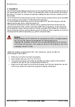
Page 5: ...äuse ist dabei ordnungsgemäß zu erden Beim Einschrauben in einen Hydraulikblock ist es ausreichend wenn der Block über das Hydrauliksystem geerdet ist Bei Wandmontage muss das Gehäuse separat geerdet werden z B geschirmte Leitung ACHTUNG Das Einschrauben des ETS 3000 mit integriertem Sensor muss mit einem passenden Maulschlüssel Schlüsselweite 27 am Sechskant des Druckanschlusses erfolgen Eine uns...

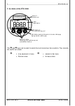
Page 6: ...en Schaltpunkt Mit den Tasten und kann zum einen der nächste bzw vorherige Menüpunkt angewählt werden zum anderen dienen sie zur Einstellung der Wert Im Menü absteigen Wert verkleinern Im Menü aufsteigen Wert vergrößern Anzeige der Druckeinheit 4 stellige Digitalanzeige LED Anzeige für aktiven Schaltpunkt Tasten zur Einstellung der Schaltpunkte Rückschaltpunkte und Zusatzfunktionen LED Anzeige dau...

Page 7: ... Messwerte auszulesen Die Mittel LED blinkt 7 Parametrierung Der Temperaturschalter kann über die Tasten am Gerät oder über die IO Link Schnittstelle mit jedem IO Link fähigen Master Konfigurationstool gemäß IO Spezifikation V1 1 parametriert werden Die IO Link Spezifikation V1 0 wird ebenfalls unterstützt Wird der eingelesene Parametersatz vom Gerät nicht akzeptiert empfehlen wir den Parametersat...

Page 8: ...er Wert Ausgang 1 fl1 FL1 Temperaturfenster oberer Wert Ausgang 2 fk2 FH2 Temperaturfenster unterer Wert Ausgang 2 fl2 FL2 Erweiterte Funktionen ef EF Rücksetzen Res RES Schaltverzögerungszeit Ausgang 1 ds1 dS1 Schaltverzögerungszeit Ausgang 2 ds2 dS2 Rückschaltverzögerungszeit Ausgang 1 dr1 dR1 Rückschaltverzögerungszeit Ausgang 2 dr2 dR2 Ausgang 1 ov1 Ou1 Ausgang 2 ov2 Ou2 Stromausgang i I Spann...

Page 9: ...ersteigt die aktuelle Temperatur die Nenntemperatur des Gerätes oder unterschreitet die aktuelle Temperatur den niedrigsten Temperaturwert so können diese nicht mehr angezeigt werden In der Anzeige blinkt die Nenntemperatur bzw der kleinste Temperaturwert Als Folge blinkt bei Anwählen des Menüpunktes Max Wert Hi der hier gespeicherte Messwert der höchsten gemessenen Temperatur entsprechend bei Anw...

Page 10: ...itierung auf die jeweilige Messbereichsober bzw untergrenze 9 1 1 Twopoint mode Einstellung auf Schaltpunkt SP Zu jedem Schaltausgang kann ein Schaltpunkt und ein Rückschaltpunkt eingestellt werden Der jeweilige Ausgang schaltet wenn der eingestellte Schaltpunkt erreicht wurde und schaltet zurück wenn der Rückschaltpunkt unterschritten wurde Beispiel für Schaltpunkt 1 Öffner und Schließerfunktion ...

Page 11: ...obere Rückschaltwert liegt knapp über dem oberen Schaltwert Der Bereich zwischen Schalt und Rückschaltwert bildet eine Sicherheitszone die verhindert dass unerwünschte Schaltvorgänge erfolgen z B bei sehr langsamen Temperaturanstieg Beispiel für Schaltausgang 1 Öffner und Schließerfunktion Abkürzungen FH 1 FH 2 High level 1 bzw 2 oberer Schaltwert 1 bzw 2 FL 1 FL 2 Low level 1 bzw 2 unterer Schalt...

Page 12: ...P und SP bzw FL und FH Schrittweite Integrierter Sensor 25 100 C 23 8 C 100 0 C 1 2 C 0 2 C 13 212 F 11 F 212 F 2 F 1 F Externer Sensor 30 150 C 28 0 C 150 0 C 2 0 C 0 5 C 22 302 F 19 F 302 F 3 F 1 F Alle in der Tabelle angegebenen Bereiche sind im Raster der Schrittweite einstellbar 9 3 Analogausgang Der Universalausgang ou2 lässt sich auf 4 20 mA oder 0 10 V entspricht Messbereich einstellen ...

Page 13: ...nstellungen Zur Anpassung an die jeweilige Applikation kann das Verhalten des ETS 3000 über mehrere Einstellungen verändert werden Diese sind zu einem Menü zusammengefasst 10 1 HAUPTMENÜ Der Bereich wird nicht angezeigt wenn in Erweiterte Funktionen unter ou2 i oder u eingestellt ist ...

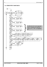
Page 14: ...14 ETS 3000 IO Link Stand 18 08 2016 HYDAC ELECTRONIC GMBH Mat Nr 669904 10 2 ERWEITERTE FUNKTIONEN Der Bereich wird nicht angezeigt wenn in Erweiterte Funktionen unter ou2 i oder u eingestellt ist ...

Page 15: ... Mat Nr 669904 10 3 ÄNDERN DER GRUNDEINSTELLUNGEN HINWEIS Bei aktiviertem Menü werden keine Schaltfunktionen ausgeführt HINWEIS Erfolgt ca 60 Sekunden lang keine Tastenbetätigung wird das Menü automatisch beendet ohne dass eventuelle Änderungen wirksam werden ...

Page 16: ... erscheint eine entsprechende Fehlermeldung die mit einem beliebigen Tastendruck quittiert werden muss Mögliche Fehlermeldungen sind E 10 Bei den abgespeicherten Einstellungen wurde ein Datenfehler erkannt Mögliche Ursachen sind starke elektromagnetische Störungen oder ein Bauteildefekt Abhilfe Mode drücken und RES mit Yes bestätigen Es erfolgt die Wiederherstellung aller einstellbaren Parameter a...

Page 17: ...tand 18 08 2016 HYDAC ELECTRONIC GMBH Mat Nr 669904 14 Anschlussbelegung M12x1 4 polig Pin Signal Bezeichnung 1 L UB 2 Q2 QA Schaltausgang SP2 Analogausgang 3 L 0 V 4 Q1 C IO Link Kommunikation Schaltausgang SP1 Q2 QA Q1 C ...

Page 18: ...0 C 13 140 F für UL Spez Lagertemperaturbereich 40 80 C 40 176 F Mediumstemperaturbereich1 40 100 C 25 100 C 40 212 F 13 212 F Zeichen EN 61000 6 1 2 3 4 Zeichen 2 Zertifikat Nr E318391 Vibrationsfestigkeit nach DIN EN 60068 2 6 bei 0 500 Hz 10 g Schockfestigkeit nach DIN EN 60068 2 27 11 ms 50 g Schutzart nach DIN EN 60529 3 IP 67 Sonstige Größen Versorgungsspannung bei Einsatz gemäß UL Spezifika...

Page 19: ...on Local User Interface Communication IO Link Revision V1 1 Unterstützung V1 0 Transmission Rate Baudrate 4 38 4 kBaud COM2 Minimum Cycle Time 2 5 ms Prozessdatenbreite 16 Bit SIO Mode Supported Yes M Sequence Capability PREOPERATE TYPE_0 OPERATE TYPE_2_2 ISDU supported Anm 4 Verbindung mit ungeschirmter Standard Sensorleitung bis zu einer maximalen Leitungslänge von 20 m möglich Download der IO D...

Page 20: ...E318391 Vibrationsfestigkeit nach DIN EN 60068 2 6 bei 0 500 Hz 10 g Schockfestigkeit nach DIN EN 60068 2 27 11 ms 50 g Schutzart nach DIN EN 60529 3 IP 67 Sonstige Größen Versorgungsspannung bei Einsatz gemäß UL Spezifikation 9 35 V DC wenn PIN2 SP2 18 35 V DC wenn PIN2 Analogausgang limited energy gemäß 9 3 UL 61010 Class 2 UL 1310 1585 LPS UL 60950 Restwelligkeit Versorgungsspannung 5 Stromaufn...

Page 21: ...tion Local User Interface Communication IO Link Revision V1 1 Unterstützung V1 0 Transmission Rate Baudrate 4 38 4 kBaud COM2 Minimum Cycle Time 2 5 ms Prozessdatenbreite 16 Bit SIO Mode Supported Yes M Sequence Capability PREOPERATE TYPE_0 OPERATE TYPE_2_2 ISDU supported 4 Verbindung mit ungeschirmter Standard Sensorleitung bis zu einer maximalen Leitungslänge von 20 m möglich Download der IO Dev...

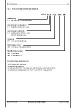
Page 22: ...sführung 2 Mit integriertem Temperaturfühler Anschlussart mechanisch 2 G1 2 A ISO 1179 2 Anschlussart elektrisch 6 Gerätestecker M12x1 4 pol ohne Kupplungsdose Ausgang F31 IO Link Schnittstelle Fühlerlänge in mm 018 100 250 350 Modifikationsnummer 000 Standard 400 Standard in F Im Lieferumfang enthalten sind 1x ETS 322X F31 XXX X00 1x Bedienungsanleitung ...

Page 23: ...12x1 4 pol Anschlussart elektrisch 6 Gerätestecker M12x1 4 pol ohne Kupplungsdose Ausgang F31 IO Link Schnittstelle Fühlerlänge in mm 000 Externer Temperaturfühler Modifikationsnummer 000 Standard 400 Standard in F Im Lieferumfang enthalten sind 1x ETS 386X F31 000 X00 1x Bedienungsanleitung 1x Kabelstecker M12x1 4 polig zum Anschluss des externen Sensors 1x Sensor Anschlusskabel 3m LIYCY 4 x 0 25...

Page 24: ...88 ZBE 06 02 4 pol Kupplungsdose M12x1 abgewinkelt mit 2m Leitung Material Nr 6006790 ZBE 06 05 4 pol Kupplungsdose M12x1 abgewinkelt mit 5m Leitung Material Nr 6006789 Farbkennung Pin 1 braun Pin 2 weiß Pin 3 blau Pin 4 schwarz 17 2 FÜR DEN MECHANISCHEN ANSCHLUSS ZBM 3000 Schelle zur Wandbefestigung anschraubbar Werkstoff Unterteil TPE Santoprene 10187 Oberteil Bandstahl DIN 95381 1 4571 Material...

Page 25: ...chelle zur Wandbefestigung anschweißbar Werkstoff Schweißlasche QSTE340TM galvanischer Überzug EN 12329 FE ZN8 B Unterteil TPE Santoprene 10187 Oberteil Bandstahl DIN 95381 1 4571 Material Nr 3184632 ZBM 3200 Spritzwasserschutz Werkstoff Elastollan S60 A15 SPF 000 Material Nr 3201919 ...

Page 26: ...Bestell Nr 906170 Technische Daten Druckfestigkeit 10 bar 145 psi Werkstoff in Kontakt mit Medium CuZn39Pb3 Messing vernickelt Tankeinbauhülse für ETS 3000 mit integr Sensor Fühlerlänge 100 mm Bestell Nr 909640 Technische Daten Druckfestigkeit 10 bar 145 psi Werkstoff in Kontakt mit Medium CuZn39Pb3 Messing vernickelt ...

Page 27: ...nge 95 5 mm Fühlerdurchmesser 6 mm Elektrischer Anschluss Stecker Binder Serie 714 M18 4 polig Kupplungsdose ZBE 03 im Lieferumfang enthalten Stecker M12x1 4 polig ohne Kupplungsdose Medienberührende Teile Messing Zeichen EN 61000 6 1 2 3 4 Sensorstrom 0 3 1 0 mA 17 3 2 Elektrischer Anschluss Kabelbuchse TFP Sensor Widerstand 1 2 3 4 1 2 3 4 ETS 386X M12x1 4 pol Geräteeinbau Stecker 4 pol Binder S...

Page 28: ...28 ETS 3000 IO Link Stand 18 08 2016 HYDAC ELECTRONIC GMBH Mat Nr 669904 18 Geräteabmessungen 18 1 ETS 3200 MIT INTEGRIERTEM SENSOR Fühlerlänge Maß Z 100 250 350 18 2 ETS 3800 FÜR EXTERNEN SENSOR ...

Page 29: ...r HYDAC Service zur Verfügung HYDAC SERVICE GMBH Hauptstr 27 D 66128 Saarbrücken Germany Tel 49 0 6897 509 1936 Fax 49 0 6897 509 1933 Anmerkung Die Angaben in dieser Bedienungsanleitung beziehen sich auf die beschriebenen Betriebsbedingungen und Einsatzfälle Bei abweichenden Einsatzfällen und oder Betriebsbedingungen wenden Sie sich bitte an die entsprechende Fachabteilung Bei technischen Fragen ...

Page 30: ...Notizen Notes Notes ...

Page 31: ...Operating instructions Translation of original instruction Electronic Temperature Switch ETS 3000 With IO Link Interface Part no 669904 Status 2016 08 18 E ...

Page 32: ...13 10 1 MAIN MENU 13 10 2 EXTENDED FUNCTIONS 14 10 3 CHANGING THE BASIC SETTINGS 15 11 Resetting the peak values 16 12 Program enable 16 12 1 CHANGING THE PROGRAM ENABLE 16 13 Error Messages 16 14 Pin Assignment 17 15 Technical Data 18 15 1 ETS 3200 WITH INTEGRAL SENSOR PROBE 18 15 2 ETS 3800 FOR EXTERNAL SENSOR PROBE 20 16 Order details 22 16 1 ETS 3200 WITH INTEGRAL SENSOR PROBE 22 16 2 ETS 3800...

Page 33: ...ate reference Please note the specifications given in this documentation regarding the instrument technology were correct at the time of publishing Modifications to technical specifications illustrations and dimensions are therefore possible If you discover errors while reading the documentation or have additional suggestions or tips please contact us at HYDAC ELECTRONIC GMBH Technical Documentati...

Page 34: ...f liability does not apply in cases of intent and gross negligence Moreover it does not apply to defects which have been deceitfully concealed or whose absence has been guaranteed nor in cases of culpable harm to life physical injury and damage to health If we negligently breach any material contractual obligation our liability shall be limited to foreseeable damage Claims due to the Product Liabi...

Page 35: ...ensor housing must be correctly grounded When fitted into a hydraulic block earthing the block via the hydraulic system is sufficient When installing on a wall the housing must be earthed separately e g with a screened cable Caution When installing the ETS 3000 with an integral sensor probe a suitable spanner AF 27 must be used on the hexagonal nut of the pressure port Inappropriate installation m...

Page 36: ...Anzeige für aktiven Schaltpunkt The and keys can be used to select the next or previous menu options They can also be used to set values One step back in menu Reduce value Ascend in the menu Increase value Display of Pressure unit 4 digit Digital display LED Display of the active switching point Buttons for setting Switching points switch back points and additional functions LED display constantly...

Page 37: ... read out measured values The centre LED flashes 7 Parameterisation The temperature switch can be parameterised via the device keys or via the IO Link interface by means of any IO Link compatible master configuration tool according IO specifications V1 1 Supports IO Link specifications V1 0 Should the read parameter sets from the device not be accepted we recommend to carry out a plausibility chec...

Page 38: ...window bottom value output 1 FL1 FL1 Temperature window top value output 2 fk2 FH2 Temperature window bottom value output 2 FL2 FL2 Add on functions ef EF Reset Res RES Switch delay time port 1 ds1 dS1 Switching delay time output 2 ds2 dS2 Switch back delay time port 1 dr1 dR1 Switch back delay time port 2 dr2 dR2 Port 1 ov1 Ou1 Port 2 ov2 Ou2 Current output I I Voltage output v U N O when hystere...

Page 39: ... lock Pr6 PrG Version Uer Ver Note If the actual temperature exceeds the unit s rated temperature or if it ranges below the bottom temperature value it can no longer be displayed The rated value or the bottom temperature value will start to flash in the display As a result when the menu point max value Hi is selected the value of the highest measured temperature respectively the lowest measured te...

Page 40: ...asuring range 9 1 1 Twopoint mode Switch point setting SP One switch point and one switch back point can be set for each switching output The particular output will switch when the pre set switch point is reached and then switch back when the level drops below the switch back point Example for switch point 1 N C and N O function Abbreviations SP1 SP2 switch point 1 switch point 2 RP1 RP2 switch ba...

Page 41: ...ted switching operations e g in the case of extremely slow temperature rises Example for switching output 1 N C and N O function Abbreviations FH 1 FH 2 High level 1 or 2 top switching value 1 or 2 FL 1 FL 2 Low level 1 or 2 lower switching value 1 or 2 FNO N O when window function is active FNC N C when window function is active Notes Setting the upper switch value FH is only possible if it lies ...

Page 42: ...ence betw RP and SP or FL and FH Increment Integral sensor probe 25 100 C 23 8 C 100 0 C 1 2 C 0 2 C 13 212 F 11 F 212 F 2 F 1 F External sensor probe 30 150 C 28 0 C 150 0 C 2 0 C 0 5 C 22 302 F 19 F 302 F 3 F 1 F All ranges shown in the table can be adjusted by the increments shown 9 3 Analog output The universal output ou2 can be set to 4 20 mA or 0 10 V corresponding to measuring range ...

Page 43: ...10 Basic Settings The ETS 3000 can be adapted to suit the particular application as required by changing multiple settings These settings are combined in a menu 10 1 MAIN MENU The range is not displayed if i or u is pre set under ou2 in the extended functions Extended functions ...

Page 44: ...14 ETS 3000 IO Link Edition 2016 08 18 HYDAC ELECTRONIC GMBH Part No 669904 10 2 EXTENDED FUNCTIONS The range is not displayed if i or u is pre set under ou2 in the extended functions ...

Page 45: ... 669904 10 3 CHANGING THE BASIC SETTINGS NOTICE When the menu is activated no switching operations are carried out NOTICE If there has been no activity in this menu for approx 60 seconds the menu will automatically close and any changes you have made will not be applied ...

Page 46: ...responding error message appears which must be acknowledged by pressing any key Possible error messages are as follows E 10 A data error has been detected in the saved settings Possible causes are strong electromagnetic interference or a defective component Action Press Mode and confirm RES by pressing Yes The factory settings will be restored for all adjustable parameters and all minimum and maxi...

Page 47: ...on 2016 08 18 HYDAC ELECTRONIC GMBH Part No 669904 14 Pin Assignment M 12x1 4 pole Pin Signal Designation 1 L UB 2 Q2 QA Switching output SP2 Analogue output 3 L 0 V 4 Q1 C IO Link communication switching output SP1 Q2 QA Q1 C ...

Page 48: ...ange 25 80 C 13 176 F 25 60 C 13 140 F acc to UL spez Storage temperature range 40 80 C 40 176 F Fluid temperature range 1 40 100 C 25 100 C 40 212 F 13 212 F mark EN 61000 6 1 2 3 4 mark 2 Certifikat No E318391 Vibration resistance to DIN EN 60068 2 6 bei 0 500 Hz 10 g Shock resistance to DIN EN 60068 2 27 11 ms 50 g Protection class to DIN EN 60529 3 IP 67 Other data Supply voltage for use acc t...

Page 49: ...cal Parameterisation Local User Interface Communication IO Link Revision V1 1 support V1 0 Transmission Rate Baud Rate4 38 4 kBaud COM2 Minimum Cycle Time 2 5 ms Process data width 16 Bit SIO Mode Supported Yes M Sequence Capability PREOPERATE TYPE_0 OPERATE TYPE_2_2 ISDU supported 4 Connection with unscreened standard sensor line possible up to a max line length of 20 m Download the IO Device Des...

Page 50: ...61000 6 1 2 3 4 mark 2 Certifikat No E318391 Vibration resistance to DIN EN 60068 2 6 bei 0 500 Hz 10 g Shock resistance to DIN EN 60068 2 27 11 ms 50 g Protection class to DIN EN 60529 3 IP 67 1 Other data Supply voltage for use acc to UL spec 9 35 V DC if PIN2 SP2 18 35 V DC if PIN2 analogue output limited energy acc to 9 3 UL 61010 Class 2 UL 1310 1585 LPS UL 60950 Residual ripple of supply vol...

Page 51: ...cal Parameterisation Local User Interface Communication IO Link Revision V1 1 support V1 0 Transmission Rate Baud Rate4 38 4 kBaud COM2 Minimum Cycle Time 2 5 ms Process data width 16 Bit SIO Mode Supported Yes M Sequence Capability PREOPERATE TYPE_0 OPERATE TYPE_2_2 ISDU supported 4 Connection with unscreened standard sensor line possible up to a max line length of 20 m Download the IO Device Des...

Page 52: ...2 2 X F31 XXX X00 Type 2 With integrated temperature probe Mechanical connection 2 G1 2 A ISO 1179 2 Electrical connection 6 Male M12x1 4 pole connector not supplied Output F31 IO Link interface Probe length in mm 018 100 250 350 Modification number 000 Standard 400 Standard in F Items supplied 1x ETS 322X F31 XXX X00 1x operating manual ...

Page 53: ...1 4 pole Electrical connection 6 Male M12x1 4 pole connector not supplied Output F31 IO Link interface Probe length in mm 000 External temperature sensor Modification number 000 Standard 400 Standard in F Items supplied 1x ETS 386X F31 000 X00 1 x operating manual 1x cable plug connector female M12x1 4 pole for the connection of the external sensor probe 1x sensor connector cable 3 m LIYCY 4 x 0 2...

Page 54: ...02 4 pole Female connector M12x1 right angle with 2m cable Part No 6006790 ZBE 06 05 4 pole Female connector M12x1 right angle with 5m cable Part No 6006789 Colour code Pin 1 brown Pin 2 white Pin 3 blue Pin 4 black 3 2 FOR MECHANICAL CONNECTION ZBM 3000 Clamp for wall mounting screw type fitting Material of lower section TPE Santoprene 10187 Material of top section Steel strip DIN 95381 1 4571 Pa...

Page 55: ...for wall mounting weld type fitting Material of welding bridge QSTE340TM zinc coating EN 12329 FE ZN8 B Material of lower section TPE Santoprene 10187 Material of top section Steel strip DIN 95381 1 4571 Part No 3184632 ZBM 3200 Splash guard Material Elastollan S60 A15 SPF 000 Part No 3201919 ...

Page 56: ...nical specifications Pressure resistance 10 bar 145 psi Material in contact with fluid CuZn39Pb3 brass nickel plated Tank mounting sleeve for ETS 3000 with integral sensor probe probe length 100 mm Order no 909640 Technical specifications Pressure resistance 10 bar 145 psi Material in contact with fluid CuZn39Pb3 brass nickel plated Protective sleeve ...

Page 57: ... Measuring range 40 125 C 40 257 F Probe length 95 5 mm Probe diameter 6 mm Electrical installation 4 pole Binder series 714 M18 ZBE 03 connector included M12x1 4 pole connector not included Parts in contact with fluid Brass mark EN 61000 6 1 2 3 4 Sensor current 0 3 1 0 mA 3 3 2 Electrical Connection 4 pole Binder series 714 M18 respectively M12x1 4 pole Cable plug connection M12x1 4 pole TFP Sen...

Page 58: ...28 ETS 3000 IO Link Edition 2016 08 18 HYDAC ELECTRONIC GMBH Part No 669904 4 Dimensions 4 1 ETS 3200 WITH INTEGRAL SENSOR PROBE Probe length dim Z 100 250 350 4 2 ETS 3800 FOR EXTERNAL SENSOR PROBE ...

Page 59: ...pairs please contact HYDAC Service HYDAC SERVICE GMBH Hauptstr 27 D 66128 Saarbruecken Germany Tel 49 0 6897 509 1936 Fax 49 0 6897 509 1933 Note The information in this manual relates to the operating conditions and applications described For applications and operating conditions not described please contact the relevant technical department If you have any questions suggestions or encounter any ...

Page 60: ...Notizen Notes Notes ...

Page 61: ...Notice d utilisation Traduction de l original Thermocontacteur Electronique ETS 3000 Avec Interface IO Link Code art 669904 Edition 18 08 2016 F ...

Page 62: ...Menu de base 13 10 1 MENU PRINCIPAL 13 10 2 FONCTIONS COMPLEMENTAIRES 14 10 3 MODIFIER LES RÉGLAGES DE BASE 15 11 Reset des valeurs Min Max 16 12 Activation de la programmation 16 12 1 MODIFICATION DE L AUTORISATION DE PROGRAMMATION 16 13 Messages d erreur 16 14 Raccordement électrique 17 15 Caractéristiques techniques 18 15 1 ETS 3200 AVEC CAPTEUR INTEGRE 18 15 2 ETS 3800 POUR SONDE EXTERNE 20 16...

Page 63: ...isation Veuillez noter que les informations fournies dans cette documentation correspondent à la technique de l appareil au moment de l élaboration de ce document Pour cette raison les différentes données techniques illustrations et mesures sont susceptibles de diverger Si lors de la lecture de cette documentation vous deviez détecter des erreurs ou encore si vous aviez des suggestions ou des rema...

Page 64: ...ette clause de non responsabilité ne s applique pas en cas de fait volontaire ou de négligence grave De plus elle ne s applique pas en cas de silence dolosif sur un vice ou aux vices dont l absence a été garantie ainsi qu en cas d atteinte fautive à la vie à l intégrité corporelle ou à la santé En cas de violation par négligence d une obligation fondamentale du contrat notre responsabilité est lim...

Page 65: ...é à la terre En cas de vissage dans un bloc hydraulique le fait que le bloc est relié à la terre via le système hydraulique est suffisant En cas de montage mural le corps doit être relié à la terre séparément par ex câble blindé ATTENTION Le vissage de l ETS 3000 avec capteur intégré doit être effectué à l aide d une clé à plate 27 sur l écrou hexagonal de l embase de raccordement Un mauvais monta...

Page 66: ...kt Avec les touches et il est possible de sélectionner les valeurs du menu sélectionné et de régler cette valeur sélectionnée Descendre dans le menu Pour diminuer Monter dans le menu Pour augmenter Affichage de l unité de pression 4 digits Affichage digitale LED de signalisation de l état des sorties digits Touches pour réglages des seuils d enclenchement seuils de déclenchement et fonctions suppl...

Page 67: ... ou pour la lecture des valeurs de mesure L indicateur DEL du milieu clignote 7 Paramétrage Vous pouvez parametrer le thermocontacteur à l aide de chaque outil de configuration IO Link par le biais des touches ou via l interface IO Link selon spécifications IO V1 1 Soutient également les spécifications IO Link V1 0 Si le jeu de paramètres enregistrés n est pas valable il est recommandé de vérifier...

Page 68: ...e sortie 1 FL1 FL1 Fenêtre de temperature du niveau valeur supérieure sortie 2 fk2 FH2 Fenêtre de temperature du niveau valeur inférieure sortie 2 FL2 FL2 Fonctions complémentaires ef EF RAZ Res RES Temporisation à l enclenchement Sortie 1 ds1 dS1 Temporisation à l enclenchement sortie 2 ds2 dS2 Temporisation au déclenchement Sortie 1 dr1 dR1 Temporisation au déclenchement Sortie 2 dr2 dR2 Sortie ...

Page 69: ...Si la température actuelle dépasse la température nominale ou si elle est inférieure à la température minimum de l appareil alors celle ci ne peut plus être affichée L affichage clignote en indiquant la température nominale ou la valeur de la temperature minimum En sélectionnant le point de menu valeur max Hi en conséquence la valeur enregistrée de la température max mésurée clignote En sélectionn...

Page 70: ...ieure ou supérieure de la plage de mesure respective 9 1 1 Twopoint mode Réglage du seuil d enclenchement SP Pour chaque sortie de commutation respectivement il est possible de régler 1 seuil d enclenchement et 1 seuil de déclenchement La sortie concernée commute lorsqu on a atteint le seuil d enclenchement et se décommute lorsqu on est en dessous du seuil de déclenchement Exemple pour point de co...

Page 71: ...ste au dessus de la valeur de commutation supérieure La plage entre le point d enclenchement et le point de déclenchement constitue une zone de sécurité qui permet d éviter les déclenchement intempestifs p ex en cas de montée très lente de la température Exemple pour sortie de commutation 1 fonction ouvrante et fermante Abréviations FH 1 FH 2 High level 1 ou 2 seuil d enclenchement supérieur 1 ou ...

Page 72: ...tance minimum entre RP et SP ou FL et FH Pas Capteur intégré 25 100 C 23 8 C 100 0 C 1 2 C 0 2 C 13 212 F 11 F 212 F 2 F 1 F Sonde externe 30 150 C 28 0 C 150 0 C 2 0 C 0 5 C 22 302 F 19 F 302 F 3 F 1 F Toutes les plages indiquées dans le tableau sont réglables en fonction du pas indiqué 9 3 Sortie analogique La sortie universelle ou2 est réglable à 4 20 mA ou 0 10 V correspond à la plage de mésur...

Page 73: ... adapter à chaque application le fonctionnement de l ETS 3000 peut être modifié à l aide de plusieurs réglages de base Ceux ci sont regroupés dans un menu 10 1 MENU PRINCIPAL La zone n est pas affichée si i ou u est réglé dans le point de menu fonctions complémentaires sous ou2 Fonctions complémentaires ...

Page 74: ...S 3000 IO Link Edition 18 08 2016 HYDAC ELECTRONIC GMBH Code art 669904 10 2 FONCTIONS COMPLEMENTAIRES La zone n est pas affichée si i ou u est réglé dans le point de menu fonctions complémentaires sous ou2 ...

Page 75: ...69904 10 3 MODIFIER LES RÉGLAGES DE BASE REMARQUE En activant ce menu les fonctions de commutations sont désactivées REMARQUE Si au bout de 60 secondes aucune touche n a été appuyée l affichage retourne à son état de fonctionnement normal sans sauvegarde des modifications ...

Page 76: ... la touche mode 13 Messages d erreur Dès que l appareil détecte une erreur un message d erreur est affiché celui ci doit être acquitté avec n importe quelle touche Les différents messages d erreurs sont E 10 Lors de la sauvegarde des réglages une erreur a été détectée Les sources de pannes peuvent être de fortes perturbations électromagnétiques ou un défaut de construction Remède Appuyer sur Mode ...

Page 77: ...6 HYDAC ELECTRONIC GMBH Code art 669904 14 Raccordement électrique M12x1 4 pôles Broche Signal Désignation 1 L UB 2 Q2 QA Sortie de commutation SP2 sortie analogique 3 L 0 V 4 Q1 C Communication IO Link sortie de commutation SP1 Q2 QA Q1 C ...

Page 78: ...lage de température de stockage 40 80 C 40 176 F Plage de température du fluide 1 40 100 C 25 100 C 40 212 F 13 212 F Sigle EN 61000 6 1 2 3 4 Sigle 2 Certificat E318391 Résistance aux vibrations selon DIN EN 60068 2 6 bei 10 500 Hz 10 g Résistance aux chocs selon DIN EN 60068 2 27 11 ms 50 g Indice de protection selon DIN EN 60529 3 IP 67 Autres valeurs Tension d alimentation Pour utilisation sel...

Page 79: ...es Paramétrage locale Interface utilisateur local Communication Révision IO Link V1 1 assistance V1 0 Transmission Rate Baudrate 4 38 4 kBaud COM2 Minimum Cycle Time 2 5 ms Etendue des données de processus 16 Bit SIO Mode Supported Yes M Sequence Capability PREOPERATE TYPE_0 OPERATE TYPE_2_2 ISDU supported 4 Connexion avec une ligne capteur standard non blindée jusqu à une longueur de max 20 m pos...

Page 80: ... Hz 10 g Résistance aux chocs selon DIN EN 60068 2 27 11 ms 50 g Indice de protection selon DIN EN 60529 3 IP 67 Autres valeurs Tension d alimentation Pour utilisation selon spécification UL 9 35 V DC avec PIN2 SP2 18 35 V DC avec PIN2 sortie analogique limited energy selon 9 3 UL 61010 Class 2 UL 1310 1585 LPS UL 60950 Oscillation résiduelle de la tension d alimen 5 Courant absorbé 0 535 A avec s...

Page 81: ...es Paramétrage locale Interface utilisateur local Communication Révision IO Link V1 1 assistance V1 0 Transmission Rate Baudrate4 38 4 kBaud COM2 Minimum Cycle Time 2 5 ms Etendue des données de processus 16 Bit SIO Mode Supported Yes M Sequence Capability PREOPERATE TYPE_0 OPERATE TYPE_2_2 ISDU supported 4 Connexion avec une ligne capteur standard non blindée jusqu à une longueur de max 20 m poss...

Page 82: ...X00 Type 2 Avec sonde de température intégrée Raccordement mécanique 2 G 1 2 A ISO 1179 2 Raccordement électrique 6 Embase M12X1 4 pôles livré sans connecteur Sorties F31 Interface IO Link Longueur sonde en mm 018 100 250 350 Numéro de modification 000 Standard 400 Standard en F Sont inclus à la livraison 1x ETS 322X F31 XXX X00 1x Notice d utilisation ...

Page 83: ...pôles Raccordement électrique 6 Embase M12X1 4 pôles livré sans connecteur Sorties F31 Interface IO Link Longueur sonde en mm 000 Sonde de température déportée Numéro de modification 000 Standard 400 Standard en F Sont inclus à la livraison 1x ETS 386X F31 000 X00 1x Notice d utilisation 1 x Connecteur M12x1 4 pôles pour le raccordement du capteur externe 1 x Câble de raccordement du capteur 3m LI...

Page 84: ...006788 ZBE 06 02 Connecteur M12x1 coudé avec 2m de câble Code art 6006790 ZBE 06 05 4 pôles Connecteur M12x1 coudé avec 5m de câble Code art 6006789 Code de couleur Pin 1 brun Pin 2 blanc Pin 3 bleu Pin 4 noir 17 2 POUR LE RACCORDEMENT MECANIQUE ZBM 3000 Collier pour fixation murale à visser Matériau partie inférieure TPE Santoprene 10187 Matériau partie supérieure acier DIN 95381 1 4571 Code art ...

Page 85: ...ation murale à souder Matériau collier à souder QSTE340TM galvanisé EN 12329 FE ZN8 B Matériau partie inférieure TPE Santoprene 10187 Matériau partie supérieure acier DIN 95381 1 4571 Code art 3184632 ZBM 3200 Protection contre les projections d eau Matériau Elastollane S60 A15 SPF 000 Code art 3201919 ...

Page 86: ...6170 Caractéristiques techniques Pression max 10 bar 145 psi Matériau en contact avec le fluide CuZn39Pb3 laiton nickelé Doigt de gant pour ETS 3000 avec sonde intégrée longueur sonde 100 mm montage dans le réservoir Code article 909640 Caractéristiques techniques Pression max 10 bar 145 psi Matériau en contact avec le fluide CuZn39Pb3 laiton nickelé doigt de gant ...

Page 87: ...5 mm Diamètre de la sonde 6 mm Raccordement électrique TFP 104 Raccordement électrique TFP 106 Embase 4 pôles Binder série 714 M18 connecteur ZBE 03 inclus à la livraison Embase 4 pôles M12x1 livré sans connecteur Matériaux en contact avec le fluide Laiton sigle EN 61000 6 1 2 3 4 Courant du capteur 0 3 1 0 mA 17 3 2 Raccordement électrique 4 pôles Binder S714 4 pôles M12x1 Connecteur M12 x 1 4 pô...

Page 88: ...ETS 3000 IO Link Edition 18 08 2016 HYDAC ELECTRONIC GMBH Code art 669904 18 Dimensions de l appareil 18 1 ETS 3200 AVEC CAPTEUR INTEGRE Longueur sonde mesure Z 100 250 350 18 2 ETS 3800 POUR SONDE EXTERNE ...

Page 89: ...à votre disposition HYDAC SERVICE GMBH Hauptstr 27 D 66128 Saarbrücken Allemagne Tél 49 0 6897 509 1936 Fax 49 0 6897 509 1933 Remarque Les indications de cette notice se réfèrent aux conditions de fonctionnement et cas d utilisation décrits Pour des cas d utilisation divergents et ou des conditions de fonctionnement différentes veuillez vous adresser au service technique compétent Pour toute ques...

Page 90: ...Notizen Notes Notes ...

Page 91: ...Notizen Notes Notes ...

Page 92: ...Notizen Notes Notes ...

Reviews: