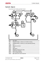
Hydraulic diagram
LVU-CD-40 /-T001
en(us)
Page 22 / 52
BeWa LVU-CD-40-T001 4142242a en-us 2016-05-13.doc
2016-05-13
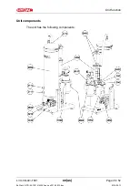
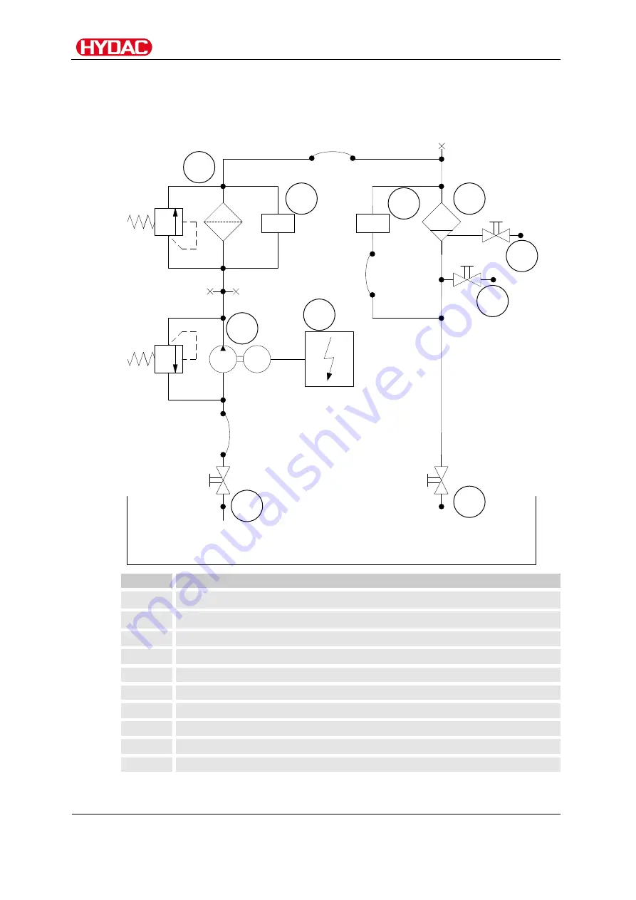
Hydraulic diagram
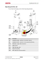
The unit has the following hydraulic circuit:
M
200
100
4000
5000
2000
3210
3350
1330
2560
7000
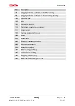
Item
Description
100
Clogging indicator, electrical, for the filter housing
200
Clogging indicator, electrical, for the coalescing housing
1330
Inlet
2000
Coalescing housing
2560
Outlet
3210
Water drain
3350
Emptying, coalescing housing
4000
Motor pump assembly
5000
Filter housing (pre-filter)
7000
Main switch with motor protection


