Unit setup/connection
LVU-CD-40 /-T001
en(us)
Page 25 / 52
BeWa LVU-CD-40-T001 4142242a en-us 2016-05-13.doc
2016-05-13
Notes on pipes/hosing
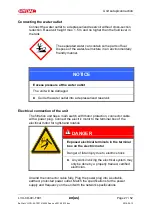
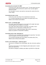
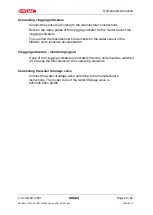
Make sure that no vibrations or stresses are carried over to the filtration unit
when connecting the piping. Make sure that no vibrations or stress/loading
from other machinery and equipment are carried over to filtration unit. Make
sure that no vibrations or stress/loading from other machinery and equipment
are carried over to filtration unit. Use hoses or expansion joints if necessary.
The pressure loss in a hydraulic line depends upon:
•
flow rate
•
kinematic viscosity
•
pipe dimensions
•
density of fluid
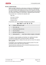
The pressure loss can be estimated for hydraulic oils as follows:
Δp ≈ 6.8 * L / d
4
* Q * V * D
Δ
p
= Pressure differential in [bar]
L
= Pipe length [m]
d
= Internal pipe diameter [mm]
Q
= Flow rate [l/min]
V
= Kinematic viscosity [mm²/s]
D
= Density [kg/dm³]
Diesel has a density of approx. 0.84 kg/dm³
This applies to straight pipelines and hydraulic oils. Additional threaded
connections and pipe bends increase the pressure differential.
Keep the height difference between the pump and the oil level in the tank as
low as possible.
Constrictions in the connections and lines should be avoided. This could
compromise suction output and cause cavitation .
Take note that the nominal size of the connected hoses/piping must be at
least as large as the inlet port sizes.

