background image


Operating the volume meter (optional accessories) 


FCC-CM 

en(us) 

Page 32 / 60 

BEWA FCC-CM 3648206 en-us 2016-07-08.docx 

2016-07-08 


Operating the volume meter (optional accessories) 

The meter housing consists of impact-resistant fiberglass-reinforced plastic. 

The electronic component is shock-proofed and sealed against oil intrusion. 

The electronics are powered by a lithium battery with an expected life of ≈ 7 

years in normal use. 
 

Replacing the battery 

The battery can be replaced. Replacing the battery must be done by trained 

personnel, since the calibration factor needs to be reprogrammed at the 

same time. 
A battery symbol indicating replacement of the battery appears before the 

battery is entirely discharged. 
 

Resetting the volume meter - RESET 

The display of the batch register memory can be set to ZERO by pushing the 

RESET button. Resetting is not possible during an operating cycle. Resetting 

the totalizer is only possible through internal programming. 
 

Functional monitoring 

The RESET command automatically triggers a self-test of the meter. The 

LCD shows all of the display segments "8". Volume pulses that come in dur-

ing the self-test phase are registered and evaluated. All the other saved val-

ues, such as unit of measurement and correction factor, are checked. Only 

when the values tally, will a normal measurement be performed. If one or 

several values do not tally, this is indicated by a number of lines ( ---- ), and 

the metering function stops. 
The measured volume and/or all measurement pulses are evaluated in each 

case and added to the last dosing volume shown, provided that a new dosing 

process has not be initiated by pressing the RESET key. 
 

Summary of Contents for FCC-CM 5/15

Page 1: ...FCC CM FluidCarrier Compact with ConditionMonitoring Operating and Maintenance Instructions English translation of original instructions Keep for future reference Document No 3648206 ...

Page 2: ...g Documentation Representative Mr Günter Harge c o HYDAC International GmbH Industriegebiet 66280 Sulzbach Saar Telephone 49 6897 509 1511 Fax 49 6897 509 1394 E mail guenter harge hydac com HYDAC FILTER SYSTEMS GMBH All rights reserved No part of this work may be reproduced in any form print photocopy or by other means or processed duplicated or distributed using electronic systems without the wr...

Page 3: ...alifications of personnel target group 12 Wear suitable clothing 13 Observe regulatory information 13 What to Do in Case of Emergency 14 Firefighting Extinguishing Fires 14 Unpacking the unit 14 Transporting the unit 15 Storing the unit 15 Decoding the name plate 16 Checking the scope of delivery 18 Characteristics of the unit 19 Filtration unit components 19 Filtration unit dimensions 21 Filtrati...

Page 4: ...brating the totals counter 33 Programming the volume meter 34 Correcting setting the measurement accuracy 36 Performing maintenance 38 Cleaning the unit 38 Tilt out the hose retainer 38 Changing the filter element 39 Change the breather filter 44 Cleaning replacing the suction strainer 45 Suction strainer cleaning interval 45 Replacing the protective screen to the Contamination Sensor 48 Errors an...

Page 5: ...al obligation our liability shall be limited to foreseeable damage Claims due to Product Liability shall remain unaffected Technical Support Contact our technical sales department if you have any questions on our product When contacting us please always include the model code serial no and part no of the product Fax 49 6897 509 9046 E mail filtersystems hydac com Product modification We would like...

Page 6: ...e which topic I am looking for WHERE can I find the information I m looking for The documentation has a table of contents at the beginning There I select the chapter I m looking for and the corresponding page number de HYDAC Filtertechnik GmbH BeWa 123456a de Seite x Produkt Kapitel 200x xx xx The documentation number with its index enables you to order another copy of the operating and maintenanc...

Page 7: ...y devices are present Secure the hazardous areas which may arise between the unit and other equipment Maintain the unit inspection intervals prescribed by law Document the results in an inspection certificate and keep it until the next in spection Hazard symbols These symbols are listed for all safety information and instructions in these operating instructions which indicate particular hazards to...

Page 8: ...avoided can result lethal or serious injury CAUTION CAUTION The signal word indicates a hazardous situation with a low level of risk which if not avoided can result in minor or moderate injury NOTICE NOTICE The signal word indicates a hazardous situation with a high level of risk which if not avoided will result in damage to property Structure of the safety information and instructions All warning...

Page 9: ...ined in the instruction manual performing inspection and maintenance work NOTICE Unpermitted operating media The filtration unit will be destroyed Use the filtration unit only in conjunction with lubricating and mineral oils and or media that are based on mineral oil or biologically fast de gradable fluids based on synthetic ester HEES Permitted operating fluids Mineral oils acc to DIN 50524 Gear ...

Page 10: ...CC CM 3648206 en us 2016 07 08 docx 2016 07 08 NOTICE Suction strainer missing operating without a suction strainer The filtration unit will be destroyed Never operate the filtration unit without a suction strainer Clean the suction strainer regularly ...

Page 11: ...ter Systems GmbH will assume no liability for any damage resulting from such use The owner alone shall assume any and all associated risk Improper use or use deviating from intended may result in hazards and or will damage the unit Examples of improper use Operation in potentially explosive atmospheres Operation under non approved operational conditions Operation when the safety devices are defect...

Page 12: ...k as instructed Operating personnel such persons have been instructed in power unit opera tion and are aware of potential hazards due to improper use Specialist personnel such persons have corresponding specialist training and several years work experience They are able to assess and perform the work assigned to them they are also able to recognize potential hazards Activity Person Knowledge Trans...

Page 13: ...killed Wear close fitting clothing Do not wear any rings chains or any other jewelry Wear work safety shoes Wear gloves Observe the information relating to personal protection equipment in the safety data sheet of the operating fluid Observe regulatory information Observe the following regulatory information and guidelines Legal and local regulations for accident prevention Legal and local regulat...

Page 14: ...hting Extinguishing Fires Use a powder extinguisher that corresponds to fire class B as per EN 2 to ex tinguish any fires Maintain a minimum safe distance from electrical components For a mains voltage of up to 1000 V the minimum safe distance is 1 m Unpacking the unit Prior to delivery the product is function and leak tested in the factory When unpacking the product check it for damage in transit...

Page 15: ...onnection chord and both hoses to the hose retainer Push the filtration unit only at the grip Transport the filtration unit upright and in secure packaging Storing the unit Drain the filter unit completely including the tank contents before putting it into storage Pull out the power plug and fasten the hoses and power cord on the hose retainer Store the unit in an upright position in a clean dry n...

Page 16: ... 2016 07 08 docx 2016 07 08 Decoding the name plate Details for identifying the filtration unit can be found on the name plates on the unit and the components Item Description 1 Name plate of filtration unit 2 Name plate of electric motor 3 Model code for details see page 52 ...

Page 17: ...Description Part No Part number S N Serial number year of production Power Power consumption Voltage Grid Voltage power supply Frequency Frequency Current Current consumption Pressure max Operating pressure maximum Weight Weight when empty Flow rate Flow rate Temp oil Permissible oil temperature range Temp amb Permitted ambient temperature range Volume Fluid volume in unit ...

Page 18: ... The FluidCarrier Compact FCC is ready for operation upon delivery Before putting the filtration unit into operation check it for possible damage The following items are supplied Qty Designation 1 FCC ready for connection with suction and pressure hose power chord including power plug 1 Operation and Maintenance Instructions this document ...

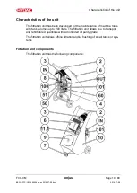
Page 19: ...een developed for the maintenance of machine tools with tank volumes up to 200 liters The filtration unit allows you to transport and refill filtered quantities with a monitored oil purity grade The filtration unit allows offline filtration and or flushing of small tanks or sys tems Filtration unit components The filtration unit has the following components ...

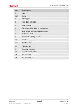
Page 20: ...t OUT Outlet 2 Sliding grip 4 Fluid level indication 3 Hose retainer 6 Electrical switch box with main switch 7 Nose wheel with immobilization brake 8 Suction strainer 9 Inspection opening for tank 10 Chassis 11 1 Breather filter 50 Filtration unit 51 Clogging indicator 60 Contamination Sensor 100 Ball valve IN 101 Ball valve OUT ...

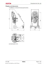
Page 21: ...Characteristics of the unit FCC CM en us Page 21 60 BEWA FCC CM 3648206 en us 2016 07 08 docx 2016 07 08 Filtration unit dimensions The filtration unit has the following dimensions All dimensions in mm ...

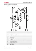
Page 22: ...ng hydraulic circuit M CS1000 DRAIN VENT DRAIN IN OUT AS1000 AS3000 OUT IN 61 60 8 59 51 100 101 50 4 11 1 Item Designation IN Inlet OUT Outlet 4 Fluid level indication 8 Suction strainer 11 1 Breather filter 50 Filtration unit 51 Clogging indicator 59 Protective screen to Contamination Sensor 60 Contamination Sensor 61 AquaSensor optional 100 Ball valve IN 101 Ball valve OUT ...

Page 23: ...us 2016 07 08 docx 2016 07 08 Setting up the unit Set up the unit in such a way that it is secured against unintentional dis placement To do so apply the parking brake on the front wheel Select the desired operating mode see Chapter Selecting operating modes on page 26 ...

Page 24: ...eposited on the bottom of the tank The greatest contamination is found on the bottom of the tank All impurities and other particles are deposited on the bottom of the tank Using the lance put the suction hose into the appropriate reservoir without tension or twist and secure the suction hose against falling out or floating Attaching connecting the pressure hose Using the lance put the pressure hos...

Page 25: ...en the suction side and pressure side tanks a suction effect can develop in the hose that is lower down caus ing the fluid levels to equalize in accordance with a principle of communi cating vessels siphoning This siphoning effect also occurs when fluid is pumped in a pre pressurized tank When the unit is switched off the height difference primary pressure can cause flow to occur both in the feed ...

Page 26: ...M 3648206 en us 2016 07 08 docx 2016 07 08 Selecting operating modes The unit has the following two operating modes Operating mode For details see page Filling the unit 27 Filtering the unit contents 28 Draining the unit 29 Flushing an external tank or system 30 ...

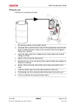
Page 27: ...n hose against falling out or floating 3 Insert the power plug into a suitable power outlet Make sure that the voltage is correct 4 Switch on the unit at the main switch 5 Monitor the level in the unit during filling using the filling level display at the back of the tank 6 Switch off the unit at the main switch once it has reached the max mark 7 Take the suction hose out of the tank and wind it a...

Page 28: ...o a suitable power outlet Make sure that the voltage is correct 3 Switch on the unit at the main switch 4 3 to 4 circulations are necessary to filter the tank contents of 70 liters For a volumetric flow of 5 l min filtration of the tank contents 1 hour 5 After filtration switch off the unit at the main switch 6 Pull the plug out of the socket and wind the connection cable at the unit 7 The unit co...

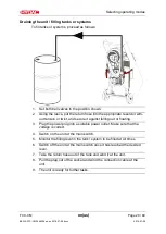
Page 29: ...sion or twist and secure it against falling out or floating 3 Plug the power plug into a suitable power outlet Make sure that the voltage is correct 4 Switch on the unit at the main switch 5 Monitor the filling level in the tank system to be filled at all times 6 Switch off the unit at the main switch once it has reached the desired level 7 Take the return hose out of the tank and wind it at the u...

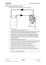
Page 30: ...ervoir without tension or twist and secure it against falling out or floating 4 Plug the power plug into a suitable power outlet Make sure that the voltage is correct 5 Switch on the unit at the main switch 6 Approx 3 to 4 circulations of the tank volume are necessary to filter the tank contents Observe the maximum volumetric flow of the unit 7 After filtration switch off the unit at the main swit...

Page 31: ...indicators depending on the version Please observe the clogging indicators as described in the following Viewing and resetting the optical clogging indicator The filter housing is equipped with an optical clogging indicator for monitoring the contamination of the filter element When the clogging indicator is red 1 change the filter element 2 Reset the clogging indicator by pressing the reset butto...

Page 32: ...the volume meter RESET The display of the batch register memory can be set to ZERO by pushing the RESET button Resetting is not possible during an operating cycle Resetting the totalizer is only possible through internal programming Functional monitoring The RESET command automatically triggers a self test of the meter The LCD shows all of the display segments 8 Volume pulses that come in dur ing ...

Page 33: ...re coming in see also calibration or correction factor The correction factor programmed at the factory shows during the basic me ter precision test with an electronic display attached Example Quantity dispensed 4 2 liters Quantity displayed 4 0 liters Correction factor k 4 2 4 0 1 05 Pressing the TOTAL and the RESET button simultaneously in this sequence will cause the programmed correction factor...

Page 34: ...rder QT GAL L PT After selecting the unit required this program section is exited by pressing the TOTAL key At the same time the measurement unit se lected in this way is saved as the current value 3 The value switched last is saved as the current value in the program by pressing the TOTAL button 4 Each time the RESET button is pressed the value will switch one fur ther from 0 9 The required value...

Page 35: ... measurement unit are saved redundantly for safety reasons The contents of the totalizer are also retained after reprogramming as long as the measurement unit is not changed If programming in point 8 is completed with a new unit the totals counter is automatically re set to zero After enabling the programming button the micro processor switches off all of the functions including the LCD display ex...

Page 36: ...utton until the first number to be changed flashes in this case 0 6 Press the RESET key repeatedly until the desired value is reached once in this case to reach 1 7 Press the TOTAL button until the next number to be changed flashes in this case the first 9 8 Press the RESET key repeatedly until the desired value is reached once in this case to reach 0 9 Press the TOTAL button until the next number...

Page 37: ...optional accessories FCC CM en us Page 37 60 BEWA FCC CM 3648206 en us 2016 07 08 docx 2016 07 08 saved program values 16 Replace the meter back onto the basic meter 17 After programming press the RESET button to activate the LCD ...

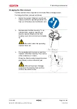
Page 38: ...orming any work Cleaning the unit We recommend cleaning the entire interior of the reservoir once a year To do so remove the tank lid and clean the interior mechanically Clean all the removed parts and examine them for any possible damage Replace components if necessary Tilt out the hose retainer To exchange the filter element remove the hoses and the power chord from the hose retainer and tilt th...

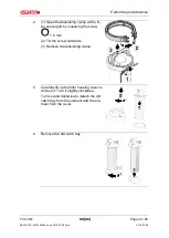
Page 39: ... out of the lines into the filtration unit 2 Depressurize the filter housing To ac complish this carefully open the air bleed screw Air Bleed on the filter housing cover do not unscrew complete ly Be careful when the operating medium flows out 3 Put a suitable tank in place to catch the medium in the filter housing The volume of the contents is 3 liters Empty the filter housing through the drain p...

Page 40: ...mp at the fil ter housing lid by loosening the screw 6 mm 2 Tilt the screw outwards 3 Remove the tensioning clamp 5 Carefully lift up the filter housing cover to remove it Turn it slightly clockwise Turn counterclockwise to detach the dirt catch tray from the element and the ele ment from the cover 6 Remove the dirt catch tray ...

Page 41: ...ord ing to local regulations and guidelines 8 Clean the removed parts and examine them for any possible damage Check the O ring on the filter bowl cover for damage Replace it if necessary Moisten the O rings on the filter bowl cover and on the new filter element with operating fluid Never use grease or other me dia 9 Now place the filter bowl cover on the new filter element and lock it in place ...

Page 42: ...f the filter element 11 Place the filter element with the cover and dirt catch tray in the filter housing Observe correct placement of the O ring on the cover while doing so 12 1 Place the tensioning clamp around the filter housing and filter lid 2 Insert the the screw 3 Tighten the screw 6 mm of the tensioning clamp with the maximum torque of 5 Nm ...

Page 43: ...16 07 08 13 Tighten the drain plug Drain on the connection part of the unit Switch the filtration unit on Bleed the filter housing through the air bleed screw Air Bleed in the filter cover 14 Check the filtration unit for leaks while it is operating The filter element change is now com plete ...

Page 44: ... environment the replacement intervals shorten ac cordingly Replace the filter element of the breather filter as follows 1 Unscrew cover 11 1 of the breather filter by hand in a counterclock wise direction 2 Remove used filter element 11 2 and dispose of it in an environmen tally correct manner 3 Insert new filter element 11 2 and screw on cover 11 1 by hand in a clockwise direction 4 Replacement ...

Page 45: ...t without a suction strainer Check clean the suction strainer regularly To protect the pump from coarse contaminant particles there is a suction strainer in the suction port Clean the suction strainer regularly Suction strainer cleaning interval The suction screen 2 42 has a much larger absorption capacity at a mesh width of 300 µm Change interval Suction strainer every 250 hours at least monthly ...

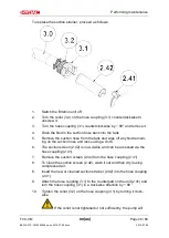
Page 46: ... fluid remain ing on the suction hose and lance using a cloth 6 The suction screen 2 42 is now visible and can be accessed via the hose coupling 2 41 7 Remove the suction screen 2 42 from the hose coupling 2 41 8 To clean the suction screen 2 42 wash it out and then dry it using compressed air 6 Insert the new or cleaned suction strainer 2 42 into the hose coupling 2 41 9 Attach the hose coupling ...

Page 47: ...M en us Page 47 60 BEWA FCC CM 3648206 en us 2016 07 08 docx 2016 07 08 take in air via the hose coupling 11 Start up the unit 12 Check the unit for leaks while it is operating 13 Checking replacing the suction screen is complete ...

Page 48: ...e ContaminationSensor will become blocked clogged Never operate the filtration unit without a protective screen Replace the protective strainer regularly A protective strainer is installed upstream of the Contamination Sensor to protect it from blocking clogging Depending on the contamination level of the medium replace the strainer regularly Item Designation 10 Protective strainer 100 µm 20 O rin...

Page 49: ...Performing maintenance FCC CM en us Page 49 60 BEWA FCC CM 3648206 en us 2016 07 08 docx 2016 07 08 ...

Page 50: ...owing spare parts are available for the unit Article designation Material p no Filter bowl repair kit comprising of Filter bowl O ring Oil discharge cap Tensioning clamp NBR 349692 OLF repair kit comprising of O rings Radial shaft seal Fastening screws NBR 3054619 Filter element N5DM002 2 µm 349494 Filter element N5DM005 5 µm 3068101 Filter element N5DM020 20 µm 3023508 Replacement pump OLF 5 4 wi...

Page 51: ... power cord to the unit Shutting down the unit See chapter Taking the unit out of operation Disposing of the unit Dispose of the packaging material in an environmentally friendly manner After dismantling the unit and separating the various materials dispose of the unit in an environmentally friendly manner Customer Service Service HYDAC Service GmbH Friedrichtaler Str 15 Werk 15 66540 Neunkirchen ...

Page 52: ... Standard in Europe according to CENELEC HD472 S1 at 50 Hz filter element N5DM002 DIMICRON filter mesh 2 µm absolute N5DM005 DIMICRON filter mesh 5 µm absolute N5DM010 DIMICRON filter mesh 10 µm absolute N5DM020 DIMICRON filter mesh 20 µm absolute N5AM002 AQUAMICRON filter mesh 2 µm absolute N5AM020 AQUAMICRON filter mesh 20 µm absolut Clogging indicator BM Differential pressure indicator optical ...

Page 53: ...imum flow rate 4 l min 15 l min Permissible viscosity range 15 200 mm s 15 200 mm s Permitted fluid temperature range 0 80 C 0 to 80 C Permitted ambient temperature range 0 to 40 C 0 40 C Permitted storage temperature range 0 50 C 0 50 C Weight when empty 63 kg 63 kg Filtration rating 2 μm absolute 2 μm absolute Contamination retention ca pacity when using filter element N5DM002 200 g ISO MTD 200 ...

Page 54: ...ll cause this declaration to lose its validity Designation Filtration unit Type FCC CM series Part no Serial no Applied directives and standards Machinery Directive 2006 42 EC article 1 1a EMC Guideline 2014 30 EU Safety of machinery DIN EN ISO 12100 1 2 Electromagnetic compatibility Immunity for industrial environ ments DIN EN 61000 6 2 Electrical equipment of machines DIN EN 60204 1 2016 04 20 D...

Page 55: ... plug 39 43 50 draining 39 E EC declaration of conformity 54 Error 50 F filling 9 27 29 31 Filter 11 50 Filter element 50 filtration 9 10 15 16 18 19 21 22 24 28 30 31 39 43 45 46 48 Filtration 19 20 21 22 53 54 Flow rate 17 Fluid level indication 20 22 G Guideline 54 H Hazard symbol 7 8 I Imprint 2 IN 20 22 In case of emergency 14 Inlet 20 22 Inspection 20 ISO 53 54 M Maintenance 1 18 Measures 8 ...

Page 56: ... en us Page 56 60 BEWA FCC CM 3648206 en us 2016 07 08 docx 2016 07 08 Spare parts 50 Specialist personnel 12 switching on 31 Synthetic ester 9 T Transport 12 15 troubleshooting 12 50 V Vane pump 52 W Weight 17 53 ...

Page 57: ......

Page 58: ......

Page 59: ......

Page 60: ...et Postfach 1251 66280 Sulzbach Saar 66273 Sulzbach Saar Germany Germany Phone 49 0 6897 509 01Central Fax 49 0 6897 509 9046 Technical De partment Fax 49 0 6897 509 577 Sales De partment Internet www hydac com E mail filtersystems hydac com ...

Reviews: