Measured values
HMG 4000
Edition 2016-03-08 - V01 R04
[39]
Part No.: 669950
7.5.1 HCSI sensors
These sensors are termed
"HCSI sensors"
(HYDAC CAN Sensor Interface) according to
the analogue HSI sensors (HYDAC Sensor Interface) for the analogue input.
If connection "
K
" is run in this mode, HCSI sensors connected to this, including all
features, will be automatically detected by the HMG 4000 and the "internal" CAN
sensor bus operated with 500 kB/s.
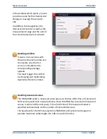
A HCSI sensor can have one or more channels. In the sensor, a channel number is
stored for every channel. A maximum of 28 channels can be allocated in the HMG 4000.
Each channel number may only appear in the bus configuration just once and can be
changed or reassigned at the HMG 4000.
In the delivery state, all sensors have the channel number "
1
", number "
2
" for sensors
with multiple channels, etc. This means that when setting up the bus connection one or
more channel numbers must be set for each sensor in order to establish a direct
reference between the physical sensor and the corresponding display in the HMG.
The allocated channel number remains saved permanently in the sensor.
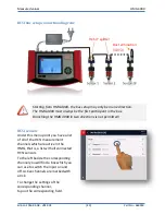
The individual sensors are connected via a 5-pin M12x1 connection cable (ZBE 30) and
"
HCSI Y splitter
".
Like with every CAN bus system, the bus line in HCSI mode needs to terminate at every
end.
In this respect, the HMG-internal load resistor in HCSI mode connects automatically and
a "
HCSI bus termination
" must be screwed onto the last sensor of the Y splitter at the
other end.
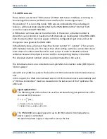
Signal update time:
The following rule of thumb can be used to calculate the signal update time of the
connected HCSI sensors:
[ms]
n = Number of connected sensors
T = Update time, rounded up to full ms
The HMG 4000 can supply power to up to 28 HCSI sensors internally when a
power supply is connected.
No separate power supply is required to set up the bus.

