Hydraulic circuit
Hydraulic circuit
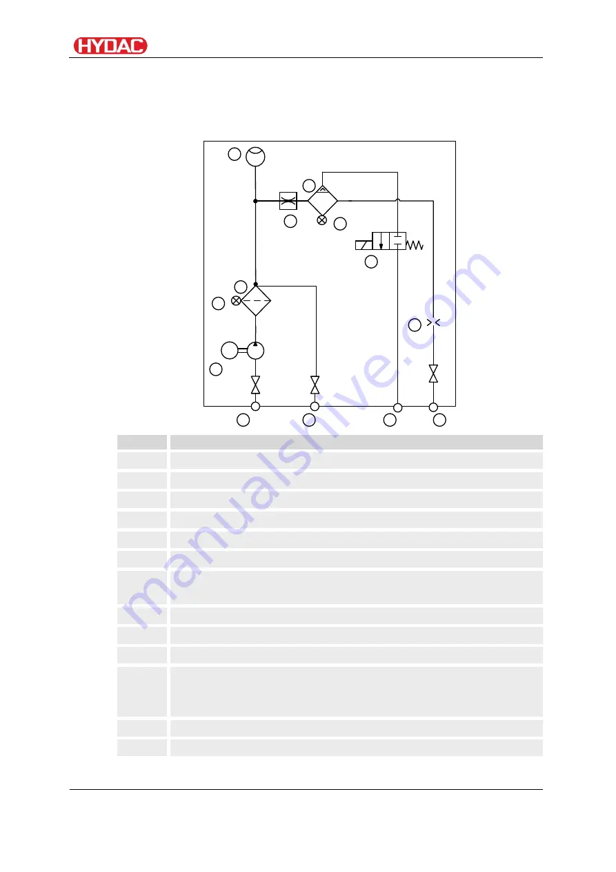
The unit has the following hydraulic diagram:
M
1
6
7
3
4
2
12
11
8
5
13
9
10
Item
Designation
1
Water entry
INLET WATER
2
Outlet Water
OUTLET WATER
3
Drain
DRAIN
4
Oil drain
DRAIN OIL
5
Motor-pump group
6
Pre-filter
7
Contamination sensor filter housing,
differential pressure indicator 2 bar
8
Flow restrictor 20 l/min
9
Flow direction mark
10
Coalescing housing
11
Contamination sensor coalescing
casing, differential pressure indicator
0.8 bar
12
Drain valve
13
Orifice
OLSW
en(us)
Page 22 / 76
BeWa OLSW 4268435 en-us 2017-11-09.docx
2017-11-09
Summary of Contents for OLSW
Page 63: ...Finding spare parts OLSW en us Page 63 76 BeWa OLSW 4268435 en us 2017 11 09 docx 2017 11 09 ...
Page 74: ......
Page 75: ......


