background image


Connecting the unit


VMU 1 ATEX II 2G IIC T4 

en(us) 

Page 32 / 60

BEWA VMU _4_ATEX-II2GIICT4_4066057 en-us 2015-10-12.doc 

2015-10-12


Make sure that no tension or vibrations are carried over to the pump or filter 
housing when the pipes are connected. Use hoses or expansion joints if 
necessary. 
 

Connecting the inlet port (IN) 

NOTICE 

Contamination too high 

The unit will be damaged 


Do not prime directly at the bottom of the tank 


Do not prime in the sump 


Never prime without a built-in suction screen 


The greatest contamination is found on the bottom of the tank. 
All impurities and other particles are deposited on the bottom of 
the tank. 

 
The suction pressure at the VMU inlet must be in the range of -0.4 ... 1 bar. 
Use a negative pressure-resistant, flexible hose or a pipe for the suction-side 
connection. 
Make sure that the cross-section of the connected hoses/piping is at least as 
large as the cross-section of the inlet/outlet port sizes. 
The shape of the tank connection should be set up in such a way that it will 
always be lower than the level of the oil in the tank. 
Install a shut-off valve on the suction side of the tank. 
 

Summary of Contents for VarnishMitigation Unit

Page 1: ...VarnishMitigation Unit VMU 4 ATEX II 2G IIC T4 Operating and Maintenance Instructions English translation of original instructions Document no 4066057 ...

Page 2: ...irector Mathias Dieter Dipl Kfm Wolfgang Haering Documentation Representative Mr Günter Harge c o HYDAC International GmbH Industriegebiet 66280 Sulzbach Saar Telephone 49 6897 509 1511 Fax 49 6897 509 1394 E Mail guenter harge hydac com HYDAC FILTER SYSTEMS GMBH All rights reserved No part of this work may be reproduced in any form print photocopy or by other means or processed duplicated or dist...

Page 3: ...ucture of the safety information and instructions 10 Observe regulatory information 10 Proper designated use 11 Explosion protection as per EU Directive 94 9 EC 14 Improper use or use deviating from intended use 15 Qualifications of personnel target group 16 Wear suitable clothing 18 Stoppage in an emergency EMERGENCY STOP 18 Transporting the unit 19 Transport with a crane 20 Transport with train ...

Page 4: ...net 35 Switching unit on off 36 Bleeding the ion exchange column 37 Bleeding the pre filter and safety filter 37 Performing maintenance 38 Depressurizing 39 Changing VME elements 40 Changing the prefilter safety filter element 44 Replacing the filling level limit switch 48 Cleaning the suction screen in the lance 49 Storing the unit taking it out of operation 50 Disposing of the unit 50 Disposing ...

Page 5: ...tion our liability shall be limited to foreseeable damage Claims due to Product Liability shall remain unaffected Technical Support If you have any questions suggestions or encounter any problems of a technical nature please don t hesitate to contact us When contacting us please always include the model type designation and article no of the product Fax 49 6897 509 9046 E Mail filtersystems hydac ...

Page 6: ... to know I determine which topic I am looking for WHERE can I find the information I m looking for The document has a table of contents at the beginning I select the chapter I m looking for and the corresponding page number de HYDAC Filtertechnik GmbH BeWa 123456a de Seite x Produkt Kapitel 200x xx xx The documentation number with its index enables you to order another copy of the operating and ma...

Page 7: ...s all the safety devices are present Secure the hazardous areas which may arise between the unit and other equipment Maintain the unit inspection intervals prescribed by law Document the results in an inspection certificate and keep it until the next inspection Hazard symbols These symbols are listed for all safety information and instructions in these operating instructions which indicate particu...

Page 8: ...4_4066057 en us 2015 10 12 doc 2015 10 12 Risk of burns due to hot surfaces Substances that are health hazards or irritants Danger from explosive atmosphere Danger of explosion in explosive atmospheres This symbol marks safety indications that refer particularly to explosion protection ...

Page 9: ... DANGER indicates a danger with a high risk and which will lead to death or serious injury if not avoided WARNING WARNING indicates a danger with a medium risk and which can lead to death or serious injury if not avoided CAUTION CAUTION indicates a danger with a low risk and which can lead to minor injury if not avoided NOTICE NOTICE indicates a danger which will lead to damage to property if not ...

Page 10: ...the signal word indicate the severity of the danger Warning instructions listed before an activity are laid out as follows SIGNAL WORD Type and source of danger Consequence of the danger HAZARD SYMBOL Measures to avert danger Observe regulatory information Observe the following regulatory information and guidelines Legal and local regulations for accident prevention Legal and local regulations for...

Page 11: ...ls by effective removal of oil aging product Varnish Proper or designated use of the product extends to the following observing all instructions contained in the instruction manual performing inspection and maintenance work operation in explosion hazard areas in accordance with explosion protected execution labelling of the power unit DANGER Exceeding the permissible surface temperature Surface te...

Page 12: ...MU must not exceed 135 C 275 F Are the following specifications on the type label of the unit permissible in connection with use in areas posing an explosion hazard on site equipment group equipment category explosion hazard subgroup temperature class Ensure that vapors gases or mists occurring at the place of operation belong to explosion groups IIA to IIC Make sure that during installation of th...

Page 13: ...ion prone areas the safety of persons and equipment depends on the observance of all relevant safety regulations The installation and maintenance personnel thus carries particular responsibility Exact knowledge of the applicable regulations and conditions is required Please note Observe the characteristic curves and measurement operating conditions of the rating plates and datum plates Damage to t...

Page 14: ... I II I 2 2G G I II IC C T T4 4 This label in particular means that utilization is permitted only for Equipment group II Potentially explosive atmospheres in which vapors or gas air mixtures are likely to occur Usage in mining is not permitted Equipment category 2G Equipment guaranteeing a high degree of safety Designated for cases in which atmospheres posing an explosion hazard from gases vapors ...

Page 15: ...ystems GmbH will assume no liability for any damage resulting from such use The risk is borne exclusively by the machine owner Improper use may result in hazards and or will damage the unit Examples of improper use Operation in potentially explosive atmospheres other than the identified one Operation with an impermissible fluid Operation at an impermissible fluid temperature ambient temperature Op...

Page 16: ...on and instructions and applicable regulations before beginning work The operating instructions and applicable regulations are to be kept so they are accessible for operating and specialist personnel These operating instructions are intended for Operating personnel such persons have been instructed in power unit operation and are aware of potential hazards due to improper use Specialist personnel ...

Page 17: ...air Decommissioning Disassembly Specialist personnel Safe handling use of tools Fitting and connection of hydraulic lines and connections Fitting and connection of electrical lines electrical machinery sockets etc Checking the phase sequence Product specific knowledge Operation Operations control Specialist personnel Product specific knowledge Knowledge about how to handle operating fluids Knowled...

Page 18: ...itting clothing Danger of getting caught Wear close fitting clothing Do not wear any rings chains or any other jewelry Wear work safety shoes Stoppage in an emergency EMERGENCY STOP In the event of an emergency turn the main switch by 90 in a counter clockwise direction to shut down the entire unit The entire system is then voltage free downstream from this switch ...

Page 19: ... around the holders provided for this purpose and fasten them in place NOTICE Using components for pushing pulling The unit will be damaged Never use the components to push or pull the unit Use the grips provided for shifting Shift the unit manually using the rollers wheels When doing so use only the grips provided on the chassis Before shifting the unit make sure to release the hand brake on the ...

Page 20: ...suitable lifting accessories to raise or lash the unit Take care to ensure that the lifting accessories do not cause any pressures to be brought to bear against the components on the unit When transporting by crane only use suitable lifting accessories band loops Transport with train truck For transport by rail or truck supports must be placed under the mobile unit so that the rollers are subjecte...

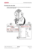
Page 21: ...ATEX II 2G IIC T4 en us Page 21 60 BEWA VMU _4_ATEX II2GIICT4_4066057 en us 2015 10 12 doc 2015 10 12 Decoding the name plate Details for identifying the filtration unit can be found on the name plates on the unit and the components ...

Page 22: ...cation of the power unit Power Power consumption electrical Voltage Grid Voltage supply power supply Current Current consumption Protections class Protection class Pressure max Maximum operating pressure Pressure IN Permissible pressure at IN port Pressure OUT Permissible pressure at OUT port Weight Weight when empty Flow Rate Flow rate Temp Oil Permitted fluid temperature range Temp Amb Permissib...

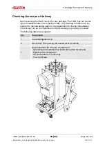
Page 23: ...ect order Any damage in transit is to be reported to the forwarding agent or the department in charge immediately the unit may not be commissioned until this damage is properly remedied The following items are supplied Qty Designation 1 VarnishMitigation Unit 2 Hand lever for opening the sealed switch cabinet 1 Documentation for the unit consisting of Operating and maintenance instructions this do...

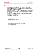
Page 24: ... of oil insoluble oil degradation products which settle in the tank in valves or in bearings These can be filterable gels or solid paint type deposits The VMU series of units are used offline The removal of varnish is based on adsorption on an active surface The advantages of the VMU are Inexpensive oil conditioning Low component wear Longer service life of the oil Quick and easy cartridge exchang...

Page 25: ...Unit components VMU 1 ATEX II 2G IIC T4 en us Page 25 60 BEWA VMU _4_ATEX II2GIICT4_4066057 en us 2015 10 12 doc 2015 10 12 Unit components The unit has the following components ...

Page 26: ...mbly 2 Prefilter 3 Ion exchange column 4 Drain DRAIN 5 Safety filter 6 Electrical switch cabinets main switch with signal lamps 7 Filling level limit switch 8 Ground cable 10 Chassis 11 Inlet IN 12 Outlet OUT 13 Ion exchange column pressure gauge 14 Ion exchange column air vent BLEED 16 Wheels 17 Swivel caster with brake 18 Sliding grip 19 Hose Cable holder ...

Page 27: ...Unit dimensions VMU 1 ATEX II 2G IIC T4 en us Page 27 60 BEWA VMU _4_ATEX II2GIICT4_4066057 en us 2015 10 12 doc 2015 10 12 Unit dimensions All dimensions in mm ...

Page 28: ... 2015 10 12 Hydraulic diagram Austritt Outlet Eintritt Inlet 3 4 Reservoir Reservoir 2 3 bar 44 psi 1 M 8 bar 116 psi 6 5 11 12 7 Item Designation 1 Motor pump assembly 2 Prefilter 3 Ion exchange column 4 Drain DRAIN 5 Safety filter 6 Electrical switch cabinets 7 Filling level limit switch 11 Inlet IN 12 Outlet OUT ...

Page 29: ...s Setting up the unit Observe the following points when setting up the unit Set up the unit horizontally on a level surface Special mounting is not required Mobile power unit activate the hand brake on the swivel casters or secure the power unit against rolling away Install the power unit in the immediate vicinity of the reservoir to be cleaned Observe the ambient temperature range of 10 40 C Make...

Page 30: ...k may not exceed a limit value depending on the respective hose type Marking the hose with the symbol M Limit value 10 2 Marking the hose with the symbol Limit value 106 The hose connection must ensure a highly conductive transition between the hose and power unit as well as between the hose and reservoir If this is not the case all conducting parts such as the metal mouth piece at the end of the ...

Page 31: ...in a hydraulic line P line depends on the following Flow rate Kinematic viscosity Pipe dimensions Fluid density The pressure loss in straight pipes P line can be calculated as follows p 6 8 L d4 Q V D p Pressure differential in bar L Pipe length m d Internal pipe diameter mm Q Flow rate l min V Kinematic viscosity mm s D Density kg dm HFD R 1 14 kg dm HFD U 0 92 kg dm Additional threaded connectio...

Page 32: ... without a built in suction screen The greatest contamination is found on the bottom of the tank All impurities and other particles are deposited on the bottom of the tank The suction pressure at the VMU inlet must be in the range of 0 4 1 bar Use a negative pressure resistant flexible hose or a pipe for the suction side connection Make sure that the cross section of the connected hoses piping is ...

Page 33: ... 1 bar is not exceeded at the outlet NOTICE OUT connection closed off The unit will be destroyed Check to be sure that all of the locking fixtures at the outlet are in open position each time before start up To prevent air from entering the medium make sure that the pressure hose with lance is always below the oil level in operation Use pressure hoses that are suitable for a pressure of at least 1...

Page 34: ...d off briefly to check the direction of rotation jog mode In the event of incorrect direction of rotation reverse the polarity of two phases When viewing from the motor fan side the direction of rotation is to the right in clockwise direction The rotating field of the connection socket must be clockwise If this is not the case then the phases can be rotated in the 16A connection plug with the aid ...

Page 35: ...ent installed Before commissioning check that all VMU elements and pre filter and safety filter elements are inserted To do so proceed as described on the pages Changing VME elements Page 40 Changing the prefilter safety filter element Page 44 Note the maximum storage time for VME elements is six months Note the expiry date on the packaging of the VME elements Control display elements on the elect...

Page 36: ...ion hose If the unit is not feeding medium after a maximum of 5 minutes of operation switch it off Pre fill the power unit using the pump or using the suction hose when the motor is off Switch the unit on again and monitor the suction action 9 3 6 12 max 5 min During operation always monitor the clogging indicator differential pressure gauge on the pre filter and safety filter so as to know when t...

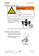
Page 37: ... the ion exchange column through the air bleed screw 1 in the cover Do not unscrew the air bleed screw 1 completely It has ventilation slots If fluid leaks out tighten the air bleed screw 1 again Bleed the housing every time you change the element or on draining Bleeding the pre filter and safety filter To bleed carefully open the air bleed screw Air Bleed on the filter housing cover If fluid leak...

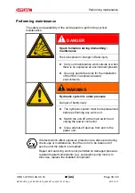
Page 38: ...he installation of the VMU in explosion hazard environments WARNING Hydraulic system is under pressure Danger of bodily injury The hydraulic system must be depressurized before performing any work on it Switch the unit off at the main switch and unplug the power connector Close all shut off devices from and to the power unit If defects which affect explosion protection are discovered during check ...

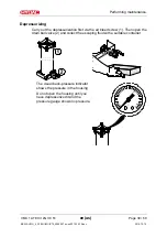
Page 39: ...Depressurizing Carry out the depressurization first via the air bleed screw 1 Then open the drain ball valve 2 and collect the escaping fluid with a suitable container The visual back pressure indicator shows the pressure in the housing Do not open the housing until you have depressurized it and the pressure gauge shows no pressure ...

Page 40: ...and their trend behavior Change the VME elements at least every 6 months You can view the current operating pressure of a maximum of 8 bars on the pressure gauge of the ion exchange column There may still be fluid in the filter bowl depending on the type of connections to the unit Let this fluid out via the lower ball valve DRAIN 1 Switch off the unit at the main switch 2 Close all shut off device...

Page 41: ...Loosen the four screws on the cover counterclockwise 6 Fold the screws down and press them against the ion exchange column This pushes the cover of the ion exchange column up 7 Take the cover off and remove the VME element 8 Clean the inside of the housing from coarse dirt as well as the sealing surfaces on the housing and the cover ...

Page 42: ...g medium Wear protective gloves when doing so 10 Put the new VME element in the housing Do not use a hammer etc 11 Check the O ring on the cover for damage and replace it if necessary Lightly wet the O ring on the cover with medium 12 Put the cover on Observe correct placement of the O ring on the cover while doing so It must not be damaged 13 Fold the four screws up and turn them clockwise evenly...

Page 43: ...57 en us 2015 10 12 doc 2015 10 12 14 Close the drain valve 15 Switch on the unit at the main switch 16 Bleed the housing through the air bleed screw in the cover Do not unscrew the air bleed screw completely It has ventilation slots Check the unit for any leaks 17 The unit is ready for operation ...

Page 44: ...lter element makes changing the filter element easier Rotate the filter element 90 clockwise or counterclockwise to separate it from the element receptacle 1 Switch off the system make sure that no operating fluid can flow out of the lines into the OLF 5 and make sure that the unit cannot be switched on again during maintenance Depressurize the filter bowl To accomplish this carefully open the dra...

Page 45: ... nut Remove the housing clamp 4 Carefully lift up the filter bowl cover to remove it Turn it slightly clockwise This ensures that the filter element remains locked on the cover Turn counterclockwise to detach the element from the cover and the dirt catch tray from the element 5 Remove the dirt catch tray 6 Remove the filter element from the filter bowl cover Dispose of the old filter element accor...

Page 46: ... rings on the filter bowl cover and on the new filter element with operating fluid Never use grease or other media 8 Now place the filter bowl cover on the new filter element and lock it in the bayonet mount 9 Attach the dirt catch tray to the lower end of the filter element and lock it in place by turning it 90 counterclockwise 10 Place the filter element with the cover and dirt catching tray in ...

Page 47: ...2015 10 12 doc 2015 10 12 12 Tighten the drain screw Drain on the connection part of the unit Switch the unit on 13 Bleed the filter bowl through the air bleed screw X in the cover Bleed the ion exchange column through the air bleed screw X in the cover 14 The prefilter safety filter is ready for operation ...

Page 48: ...age 48 60 BEWA VMU _4_ATEX II2GIICT4_4066057 en us 2015 10 12 doc 2015 10 12 Replacing the filling level limit switch When replacing the filling level limit switch 7 observe the position of the sensors A Align the sensor A parallel to the direction of flow ...

Page 49: ...ction strainer regularly To protect the pump from coarse contamination or foreign bodies a suction screen is installed in the suction lance Clean the suction strainer at regular maintenance intervals Check Clean the suction strainer immediately in the event of insufficient suction or delivery action Clean the suction strainer by washing it out or by blowing it out with compressed air 1 2 3 4 5 6 I...

Page 50: ...l power plug Wrap up the power cord and fasten it securely on the unit Store the unit in a clean dry environment The storage temperature range is 0 60 C Disposing of the unit Dispose of the packaging material in an environmentally friendly manner After dismantling the unit and separating the various materials dispose of the unit in an environmentally friendly manner Disposing of VME filter element...

Page 51: ...s Page 51 60 BEWA VMU _4_ATEX II2GIICT4_4066057 en us 2015 10 12 doc 2015 10 12 Spare parts The following are illustrations of the individual parts with positioning Not all individual parts can be supplied as spare parts available on request ...

Page 52: ... Clogging indicator visual 2 Clogging indicator electrical 1 O ring 2 634517 Ball valve for draining 1 551093 O ring between subplate and housing 4 611847 O ring between subplate and cover 4 611848 Pressure gauge 4 39173 Lance set for connection to hose 2 3455618 Hose assembly 2 Hose assembly 2 Chassis part 2 613195 Hose assembly 1 Rubber buffer 4 Pressure relief valve 1 Motor pump group type spec...

Page 53: ... Permissible suction pressure pump 0 2 to 1 bar Viscosity range 15 80 mm s Permissible operating fluid Mineral oil Connection IN OUT 22L M30x2 male thread Pump type Gear pump without Electrical data Power supply voltage see ordering details Power consumption 0 25 0 6 kW 16 A Protection class to DIN 40050 IP 55 Ambient conditions operating temperature range 0 40 C 32 104 F Storage temperature range...

Page 54: ...4066057 en us 2015 10 12 doc 2015 10 12 General data Length of suction pressure hose only version S5D5 SKDK 5 m Length of connection cable only versions PKZ FA1 FA2 10 m Noise level at 1m 80 db A Weight when empty 350 kg Required fluid cleanliness ISO 19 17 14 according to ISO 4406 1999 ...

Page 55: ...0 Hz 3 Ph O 460 V 60 Hz 3 Ph X Other voltages on request z Without electro motor Prefilter 1 Pre filter OLF 5 top loader z Without pre filter Clogging indicator BM Differential pressure indicator optical VM2BM 1 for pre filter and protective filter C Differential pressure indicator electric VM2C 0 for pre filter Differential pressure indicator optical VM2BM 1 for protective filter Supplementary de...

Page 56: ...ler Straße 15A 66540 Neunkirchen Heinitz Telephone 49 6897 509 883 Fax 49 6897 509 324 E Mail service hydac com USA HYDAC Technology Corporation HYCON Division 2260 City Line Road USA Bethlehem PA 18017 P O Box 22050 USA Lehigh Valley PA 18002 2050 Telephone 01 610 266 0100 Fax 01 610 231 0445 E Mail sales hydacusa com Internet www hydacusa com EU Declaration of Conformity The EU declaration of co...

Page 57: ... 15 52 Filter element 52 filtration 21 22 Flow rate 22 31 55 Forwarding agent 17 G Gear pump 53 55 H Hazard symbol 3 7 HFD 31 Hydraulic data 53 Hydraulic diagram 3 28 I Imprint 2 3 IN 4 22 26 28 31 32 40 53 Inlet 26 28 installation 12 13 17 38 42 44 Internal pipe diameter 31 IP 53 ISO 54 L Limit value 30 M Maintenance 1 17 Measures 10 Mineral oil 53 Model code 4 22 55 Motor pump assembly 26 28 mou...

Page 58: ... 3 9 signal words 10 Size 55 Spare part 4 51 Spare parts 4 51 Specialist personnel 16 17 Storage temperature 53 Storage temperature range 53 Suction screen 49 switching on 36 T Temperature 14 Test certificate 23 to shut down 18 Transport 3 17 20 transporting 19 20 Troubleshooting 17 V Varnish 11 24 Viscosity 53 W Weight 22 54 ...

Page 59: ......

Page 60: ...et Postfach 1251 66280 Sulzbach Saar 66273 Sulzbach Saar Germany Germany Phone 49 0 6897 509 01 Central Fax 49 0 6897 509 9046 Technical Department Fax 49 0 6897 509 577 Sales Department Internet www hydac com E mail filtersystems hydac com ...

Reviews: