HREI
Inst Issue 1: 09.05.16
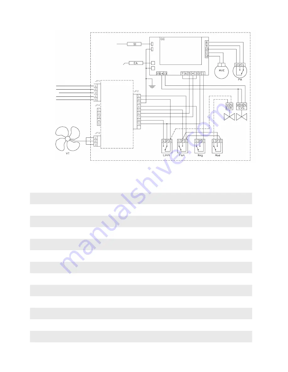
4.7 Electrical diagram
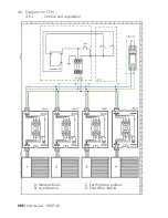
Live (brown)
Neutral (blue)
Earth (green-yellow)
Pilot (black)
Default (grey)
4.7.1
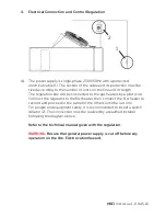
The temperature sensor of the burner modulation thermostat
(Mod) is placed on the fan’s protection grille.
VT
Blowing fan
RFP
Pilot wire receptor
Limit
Overheat thermostat with manual reset
Fan
Thermostat for fan start up
Reg
Thermostat for burner regulation
Mod
Thermostat for burner modulation (2 stages option)
CC
Control box with isolation transformer
MVE
Extractor fan
PA
Burner air pressure
SI
Ionization probe
EA
Ignition probe
EVR
Modulating gas valve (2 stage option)
EVG
Gas valve


