background image

HREI

 Inst Issue 1: 09.05.16

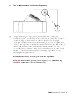
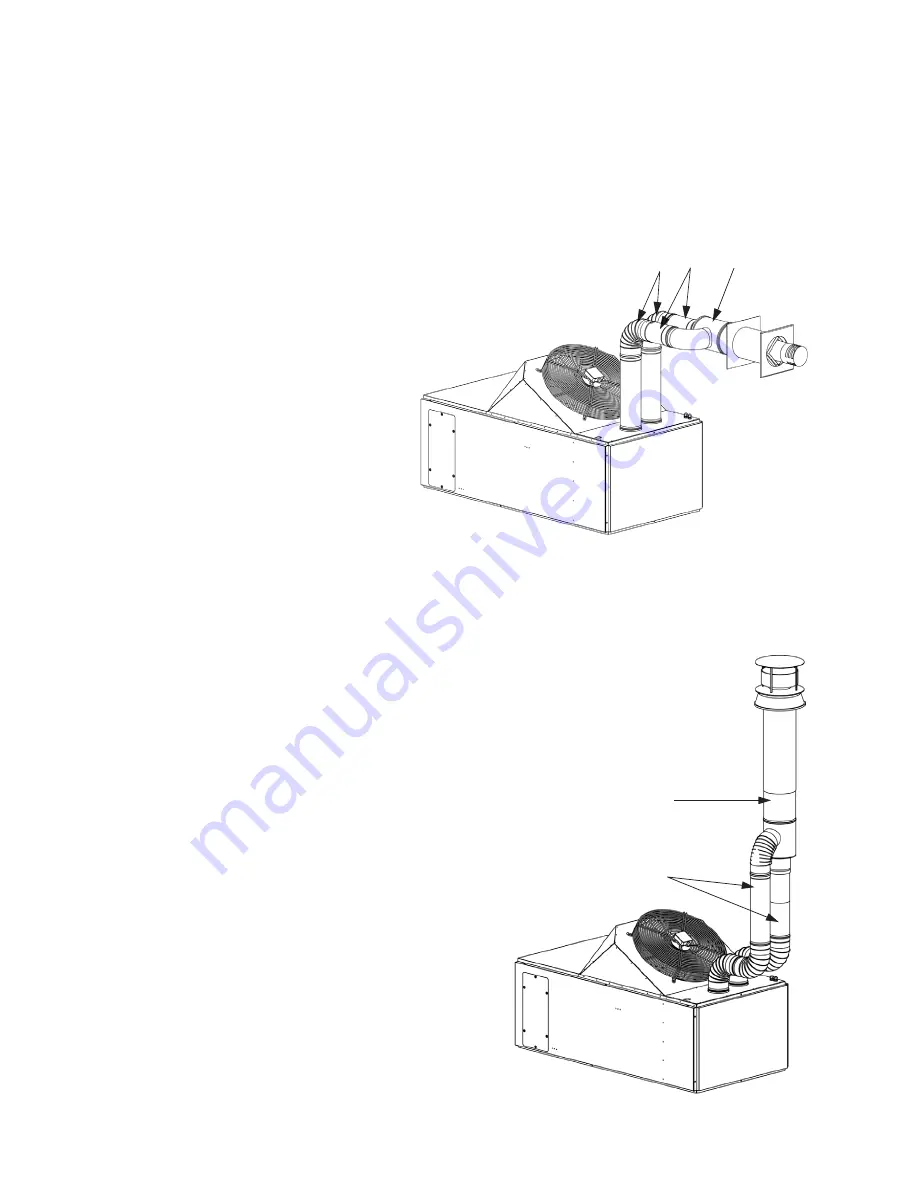
5.3  Concentric Flue Kit Connection. The connection for combustion air intake 
 

and smoke exhaust is made horizontally or vertically towards the outside 


of the room.


WARNING 

The fumes condensates should not flow inside the unit,  


risk of corrosion. If it is needed, foresee a condensate collector. In case  


of horizontal concentric installation, foresee a slope of 2° minimum and 


opposed to the unit to drain the condensate.

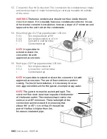
5.4  Mounting type C12: Flue pipe diameter: 130 mm
 

5.4.1 

Two single elbows at 90°


5.4.2 

Two single extensions of 1 m 


5.4.3 

Concentric wall terminal


•   

Condensate trap


NOTE 

It is possible to  


extend or divert the  


concentric kit with 


approved accessories.

5.5  Roof type C32: Flue pipe diameter: 130 mm
 

5.5.1 

Two single extensions


5.5.2 

1 concentric roof terminal 


•   

Condensate trap


NOTE 

It is possible to extend or divert the concentric kit with  


approved accessories. The use of flues involves a perfect  


sealing. To check the installation, it is necessary to use a  


non-aggresive libricant for the gasket, example: soapy water.


NOTE 

The junctions must be sealed and rigid. The  


section of flue must be at least equal to the diameter  


of the heater outlet. The smoke exhaust cannot be  


vertical or at 45° minimum. The total length of the  


connection cannot exceed 6 m, knowing that:  


elbow 90" or 45° = 1 m of flue. If the outside  


part of the flue is higher than 2m, 


foresee an insulated pipe.


3

2

1

2

1

Summary of Contents for HCBI50

Page 1: ...n the CE Certification and Hydor s warranty being cancelled 1 General 1 1 It is important these Installation and Maintenance Instructions are fully adhered to 1 2 Full details of the unit supplied are shown on the product nameplate If in doubt about any detail contact Hydor or its agents for clarification 1 3 All electrical installation must be carried out by a suitably qualified and competent per...

Page 2: ...ply during installation and maintenance The fan must be earthed in accordance with the local regulations 2 Technical Characteristics 2 1 CBI Model The HCBI heaters are equipped with an axial fan They are designed for direct blowing into the room They can be suspended or equipped with supports for installation on the floor 2 2 Performance of CBI gas unit heater Code Throw Gas Flow Natural G20 20 mb...

Page 3: ...0 130 HCBI98 130 130 Code Electrical Power W Electrical Current A Operating Temperature C Weight kg HCBI50 470 2 1 0 40 140 HCBI76 760 3 4 0 40 200 HCBI98 890 4 0 40 225 2 3 Dimensions E F B A C D G Code A B C D E F G Weight kg HCBI 50 1791 638 617 1026 130 130 3 4 140 HCBI 76 1791 892 617 1026 130 130 3 4 200 HCBI 100 1791 1146 617 1026 130 130 3 4 225 ...

Page 4: ...a complete unit with accessories 3 2 If there are any queries concerning the equipment Hydor should be contacted prior to the installation 3 3 The HCBI heaters can be installed suspended from secure fixings or supported on a suitable frame fixed to the floor They are designed to blow directly into the room and are equipped with an axial fan 3 4 Ensure there is free space around the heater and for ...

Page 5: ...to make sure of the support s strength The unit is equipped with 4 MS threaded inserts on the top to can be suspended It is necessary to used slings or threaded rods adapted to the weight of the unit The mounting must be perfectly aligned as shown on the drawing here below Be careful make sure to always use lock nuts to ensure the fastening ...

Page 6: ...pension rods are suitable to take the weight of the heater model safely These moutings must be perfectly aligned with the unit as per following drawing Present 4 feet and secure with screws M8 3 7 If the heater is to be placed on feet refer to the drawing below WARNING Support must be perfectly level check the horizonal level of the heater Attach the feet to the ground to prevent it from being mov...

Page 7: ...ed to the gas heaters by a pilot wire Connect the regulator to the first heater then connect the first heater to second and proceed in the same for the others until the last one For people and equipment safety it is recommended to install a switch isolator 2 The connection must be realized by a qualified installer following the diagram above Refer to the technical manual given with the regulation ...

Page 8: ...lar inspection of the brooder should be carried out to ensure it is operating correctly 4 4 Thermostat with remote probe Control box with programmable touchscreen and remote probe This regulation can manage up to 6 heaters The use of a remote probe allows you to install the control box outside the managed area This box has also a default light which is possible to connect However if the thermostat...

Page 9: ...HREI Inst Issue 1 09 05 16 A Neutral blue B Live brown C Earth green yellow D Pilot black 4 5 Diagram connection E N L A Neutral blue B Live brown C Earth green yellow D Pilot Wire black ...

Page 10: ...HREI Inst Issue 1 09 05 16 4 6 Diagram for CTM 4 6 1 Control and regulation A Neutral blue B Live brown C Earth green yellow D Pilot Wire black E N L ...

Page 11: ...HREI Inst Issue 1 09 05 16 4 6 2 Control regulation and default E N L A Neutral blue B Live brown C Earth green yellow D Pilot Wire black E Default grey ...

Page 12: ... fan s protection grille VT Blowing fan RFP Pilot wire receptor Limit Overheat thermostat with manual reset Fan Thermostat for fan start up Reg Thermostat for burner regulation Mod Thermostat for burner modulation 2 stages option CC Control box with isolation transformer MVE Extractor fan PA Burner air pressure SI Ionization probe EA Ignition probe EVR Modulating gas valve 2 stage option EVG Gas v...

Page 13: ... 2 3 Single roof terminal NOTE The roof outlet must be located at least at the ridge height WARNING Not Suitable for poultry houses NOTE Foresee a sufficient ventilation in the room The required fresh air for combustion must be at least of 100m h unit The section of flue must be at least equal to the diameter of the heater outlet The smoke exhaust cannot be vertical or at 45 minimum The total leng...

Page 14: ...OTE It is possible to extend or divert the concentric kit with approved accessories 5 5 Roof type C32 Flue pipe diameter 130 mm 5 5 1 Two single extensions 5 5 2 1 concentric roof terminal Condensate trap NOTE It is possible to extend or divert the concentric kit with approved accessories The use of flues involves a perfect sealing To check the installation it is necessary to use a non aggresive l...

Page 15: ... a qualified professional person Changing the gas is carried out in the following manner 6 1 1 Disconnect the electrical supply connector and close the gas inlet 6 1 2 Unscrew the gas line fixing nut Item 1 on the gas valve and also the three screws Item 2 which retain the injector ramp on the burner block 6 1 3 Change the injectors see adjustment table 6 1 4 Screw in the new injectors Item 3 chan...

Page 16: ... and to close the pressure test point 6 2 5 Check for sealing after making the adjustment 6 2 Adjustment table for stage 1 valve Types CBI 50 CBI 76 CBI 98 Adjustment for G20 Regulator Pressure Low Speed 4 5 4 5 4 5 High Speed 7 7 5 7 5 Gas ramp injectors 8 x AL 2 50 12 x AL 2 50 16 x AL 2 50 Extractor washes 35 30 Adjustment for G25 Regulator Pressure Low Speed 5 5 5 5 5 5 High Speed 9 5 10 10 Ga...

Page 17: ...4 5 Gas ramp injectors 8 x AL 2 50 12 x AL 2 50 16 x AL 2 50 Extractor washes 35 30 Adjustment for G25 Regulator Pressure 5 5 5 5 5 5 Gas ramp injectors 8 x AL 2 50 12 x AL 2 50 16 x AL 2 50 Extractor washes 35 30 Adjustment for G31 Regulator Pressure 13 13 13 Gas ramp injectors 8 x AL 1 50 12 x AL 1 50 16 x AL 1 50 Extractor washes 35 30 ...

Page 18: ...g on the type and the flow of gas and the length of the piping It is necessary to make sure that pressure drops in the piping do not exceed 5 of the supply pressure The gas connections must be made in conformity with the recommendations for indoor WARNING before opening the gas network check the sealing up to the unit heater solenoid valve Gas connection A Over 50mbar natural gas supply B Under 50...

Page 19: ...he lack of cooling can necessitate to reset the overheating thermostat and can damage the heat exchanger over the long term This commissioning must be carried out by a Qualified Technician with a current Gas Care Certificate 7 2 Initial operation 7 2 1 To commission the heater switch on the heater and turn the regulator to demand The control box tests the break contact of the air pressure switch a...

Page 20: ...at exchanger smoke extractor and venturi 9 3 1 Unscrew and open the blowing grille and the upper access door to clean the heat exchanger 9 3 2 To get access to the rear of the heat exchanger bends unscrew the 2 metal plates on the lateral sides 9 3 3 Clean the smoke extractor and the venturi by opening the burner compartment door 9 3 4 Fan Clean it with compressed air 9 3 5 Flue pipe Dismantle the...

Page 21: ...mpartment or the fan with high pressure jet Do not get wet the electrical parts ELECTRICAL HAZARD Do not spray through the doors it can damage the door gasket Do not spray directly on temperature sensors 10 Troubleshooting 10 1 In case of problems make sure that the conditions required prior to operating the heater are present If the control box is in the safety position with the burner defect ind...

Page 22: ...sition the burner default lights Gas valve defective Control box defective Ionization sensor incorrectly adjusted or defective Air in the piping No gas Replace it Adjust it Bleed the piping Check the pressure The unit tunrs on safety position red LED switched on Gas supply interrupted Reset by pressing the red button on the control box Cold air when starting Incorrect adjustment of internal thermo...

Page 23: ...f problems Problems Remedies Smell of gas Close the external gas valve and the electricity supply then warn the main tenance technician The burner stays in safety position burner defect led is lighted Press the reset button of the burner located on thermostat control box If the problem persists contact the after sales technician 11 6 If you smell gas immediately close the external gas valve to iso...

Page 24: ... safe distance around the gas heater 12 4 Never make any modifications which should always be done by a Certified Technician 12 5 Warn the Maintenance Technician of any changes to the gas gas pressure or the modification to power supply system You are strongly recommended to take out a maintenance contract with your Installer or a Certified Gas Care Technician Hydor are able to offer this Service ...

Page 25: ...s Note Number carriage paid for further examination Hydor Ltd Hydor Unit 8 Parkers Close Downton Business Centre Downton Salisbury Wiltshire SP5 3RB UK Tel 44 0 1725 511422 Fax 44 0 1725 512637 Email info hydor co uk Web www hydor co uk idealair group Unit 1 Building 1 Sydney Corporate Park 85 O Riordan Street Alexandria NSW 2015 Tel 61 02 8073 3310 Fax 61 02 8073 3320 Email info idealairgroup com...

Reviews: