background image

HydraConnect LLC

Page 6

www.hydraconnect.com

(

 720-583-4364

Product Operation

The transmitter and receiver modules have no user adjustments or controls - they 

are fully self configuring and automatically adjust themselves to the environment.  

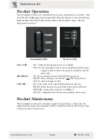
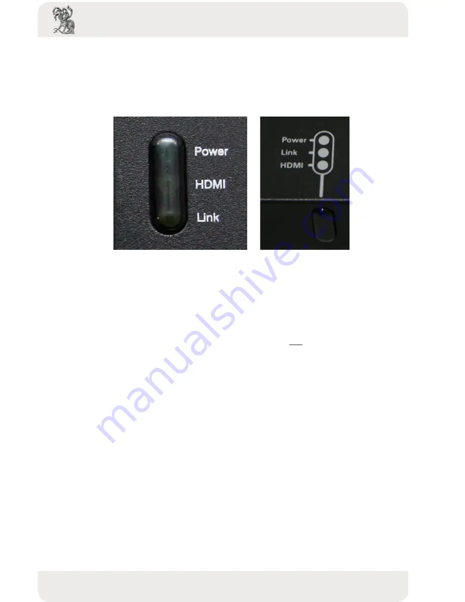
Both modules have three LEDs which indicate the module’s status.  They are 

interpreted as follows: 


                            Transmitter LEDs                                 Receiver LEDs

Power LED:


ON:  Indicates that proper power is available


OFF: On the transmitter, power is not available from the power  


supply; on the receiver, no power is available over the   

   link 

cable

HDMI LED: 

ON: Data is being received and is HDCP protected


BLINK: Data is being received and is not HDCP protected


OFF: No data is being received

Link LED: 

ON: Link connection is good and unit is powered up


BLINK: Link connection is good and unit is powered down


FLICKER: Connection cannot be established


OFF: No communication between transmitter and receiver

Product Maintenance

The transmitter and receiver modules require no maintenance.  However, the 

units should be kept clear of liquids and the ventilation slots should be kept clear 

of dust and other obstructions.

Summary of Contents for HEXT-21b

Page 1: ...www hydraconnect com 720 583 4364 HydraConnect LLC HEXT 21b HDBaseT HDMI Extender ...

Page 2: ...onnections 3 Transmitter Module Connections 3 Receiver Module Connections 3 Product Installation 4 Product Operation 6 Product Maintenance 6 Cable Pinouts 7 IR Cables 7 Link Cable 7 HDMI Cable 7 Technical Specifications 9 Warranty 10 Limited Warranty 10 Customer Remedies 10 No Other Warranties 10 No Liability For Damages 10 Rev 1 1 ...

Page 3: ...he air ventilation openings Only mount the equipment per HydraConnect s instructions Ensure that all IR connections are made BEFORE power is applied to either module Failure to observe this requirement may result in damage to the modules that will not be covered under warranty NOTE This equipment has been tested and found to comply with the lim its for a Class B digital device pursuant to Part 15 ...

Page 4: ...nd Deep Color Fully compliant with HDCP Fully 3D Compatible all 7 formats including the most popular e g Frame Packing Side by Side Top to Bottom Supports all latest Audio formats such as Dolby True HD DTS master etc Supports bi directional IR pass through of all frequency band hardware 20K 80KHz all protocols Supports 10 2Gbps HD source signal 4Kx2K Operates over standard CAT5e 6 UTP STP link cab...

Page 5: ...o be linked to the Receiver module 4 HDMI IN Connect to a HDMI source with a HDMI male male cable 5 IRDA In Infrared 3 5mm socket for plugging in the IR receiver Receiver Module Connections 1 IRDA Out Infrared 3 5mm socket for plugging in the IR flasher 2 CAT5e 6 IN Plug in a Cat 5e 6 cable that needs to be linked to the Transmitter module 3 HDMI OUT Connect to a HDMI Display with a HDMI male male...

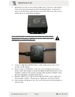
Page 6: ...her or Receiver to the designated connectors NOTE THAT INSTALLING AN IR FLASHER OR RECEIVER INTOTHEWRONGCONNECTORMAYDAMAGETHEMOD ULEWHICHWILLNOTBEREPAIREDUNDER WARRANTY 4 If an automation system IR passthrough is needed connect a 3 5mm mono connector cable between the output of the automation system and the IR input on the transmitter Connect the IR flasher to the IR output on the receiver NOTE Un...

Page 7: ...ON A VERTICAL WALL FOR PROPER OPERATION AS SHOWN BELOW 7 Connect a High Speed HDMI Male to Male cable between the receiver module and the display 8 If used connect an IR Flasher or Receiver to the designated connectors NOTE THAT INSTALLING AN IR FLASHER OR RECEIVER INTO THE WRONG CONNECTOR MAY DAMAGE THE MODULE WHICH WILL NOT BE REPAIRED UNDER WARRANTY 9 Plug the output power cable from the suppli...

Page 8: ...not available from the power supply on the receiver no power is available over the link cable HDMI LED ON Data is being received and is HDCP protected BLINK Data is being received and is not HDCP protected OFF No data is being received Link LED ON Link connection is good and unit is powered up BLINK Link connection is good and unit is powered down FLICKER Connection cannot be established OFF No co...

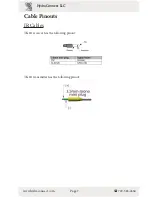
Page 9: ...Page 7 www hydraconnect com 720 583 4364 HydraConnect LLC Cable Pinouts IR Cables The IR receiver has the following pinout The IR transmitter has the following pinout ...

Page 10: ...P cable in solid core types 350MHz CAT 6 cable is preferred for best results HDMI Cable The HDMI cable has the following pinout Pin 1 TMDS Data2 Pin 2 TMDS Data2 Shield Pin 3 TMDS Data2 Pin 4 TMDS Data1 Pin 5 TMDS Data1 Shield Pin 6 TMDS Data1 Pin 7 TMDS Data0 Pin 8 TMDS Data0 Shield Pin 9 TMDS Data0 Pin 10 TMDS Clock Pin 11 TMDS Clock Shield Pin 12 TMDS Clock Pin 13 CEC Pin 14 Reserved Pin 15 SCL...

Page 11: ... 2 Gbps ӹ ӹ CEC and EDID Pass through ӹ ӹ Bi directional IR pass through Signal distance from extender output up to 40 feet 15 meters Frequency support 20KHz to 80KHz Protocol support any protocol ӹ ӹ Recommended link cable is CAT5e UTP STP CAT 6 FTP cable in solid core ӹ ӹ Power source 24VDC 36A 8 6W 100 240V AC input power supply ӹ ӹ Power consumption 8 watts operating 2 watts standby ӹ ӹ Approv...

Reviews: