background image

Page 1-5: General Information

Boxxer H

2

O

Responsibilities

The

 Purchaser’s 

responsibilities are:

Prior to arrival of unit, install 5/8” exterior plywood flooring in the vehicle and cover it with
artificial turf.

In Dodge vans the fuel tanks are located directly against the floor.  Caution must be used
when drilling any holes through the floor. (See Product Support Bulletin 94062 at the end
of this manual.)

To purchase heavy duty 24- 60 amp hour battery and have the battery ‘slow’ charge if new.

If the battery is not fully charged, damage can occur to the engine charging regulator.

Reading of owner’s manual: 

 It is the purchaser’s responsibility to read the unit opera-

tion manual and to familiarize himself with the information contained therein.

Special attention should be paid to all Cautions and Warnings.

The

 Sales Representative’s responsibilities are:

ACCEPTANCE OF SHIPMENT:

1. If the unit shows any outward signs of damage, do not sign the delivery

receipt until you have closely inspected the unit and noted any damage
on the delivery receipt.

2. The salesman from whom you purchased your unit is responsible for

supervising  the correct installation of the unit in your vehicle and thor-
oughly training you in its operation, maintenance and precautions.

Summary of Contents for Boxxer H2O

Page 1: ...ight 2006 HYDRAMASTER Corporation Mukilteo Washington MAN 182 136 No part of this manual may be reproduced or used in any form or by any means i e graphic electronic photocopying or electronic retriev...

Page 2: ...ons 1 12 MACHINE SPECIFICATIONS Section 2 Machine Layout 2 2 OPERATING INSTRUCTIONS Section 3 MACHINE MAINTENANCE Section 4 Maintenance Log MACHINE ASSEMBLIES AND PARTS LIST Section 5 VACUUM SYSTEM Se...

Page 3: ...ly Front View Right Side 5 2 Fig 5 3 Frame Assembly Front View Left Side 5 3 Fig 5 4 Frame Assembly Front View Right Side 5 4 Fig 5 5 Engine Assembly 5 6 Fig 5 6 Blower Assembly 5 8 Fig 5 7 Dash Assem...

Page 4: ...Boxxer H2 O Owner s Manual Boxxer H2 O Quick Reference Fuel Pump Assembly B4627 Rev...

Page 5: ...oven in other HydraMaster Truckmounts and this new machine was put together with an eye towards simple quick maintenance All service points are conveniently located so routine maintenance takes only a...

Page 6: ...uses this symbol throughout the manual to warn of possible injury or death This symbol is used to warn of possible equipment damage Hours Telephone Numbers Monday Friday 425 775 7276 Parts 8 00 am to...

Page 7: ...nits employing internal combustion engines must not be enclosed within a van with doors and windows closed Excessive temperatures within the engine will result in premature engine failure and a compro...

Page 8: ...icle CARBON MONOXIDE This unit generates toxic fumes Position the vehicle so that the fumes will be directed away from the job site Do not park where exhaust fumes can enter a building through open do...

Page 9: ...damage can occur to the engine charging regulator Reading of owner s manual It is the purchaser s responsibility to read the unit opera tion manual and to familiarize himself with the information cont...

Page 10: ...oil levels prior to staring the unit Starting the unit to check the engine and see that all systems function normally Checking all hoses wands etc for correct operation TRAINING A thorough review of...

Page 11: ...machine Be cautious when drilling any holes through the van floor Many vans have critical components mounted directly below the van floor that could be dam aged by a misplaced drill bit See Product S...

Page 12: ...this location partly limits working access it does direct the noise away from the cleaning site Some cleaners in the colder areas prefer this location because it puts the weight over the rear wheels...

Page 13: ...r crash will cause the machine to rocket forward Protect yourself and the machine SECURE IT It is recommended by the manufacturer that the exhaust from the front of the machine be vented down under th...

Page 14: ...most states Transportation in a vehicle of any vented fuel container that presently holds or has ever held a flammable liquid is strictly forbidden by HydraMaster Cor poration and by federal and stat...

Page 15: ...for elevations from 0 3 000 feet Any time the machine is operated above 3 000 feet there are two areas on the machine the may need adjustment The first area is the carburetor jet The higher the elevat...

Page 16: ...oilet laundry drain RV dump etc Permission should first be obtained from any concerned party or agency One disposal method which usually complies with the law is to accumulate the waste water and haul...

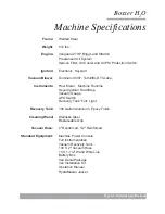
Page 17: ...ill M D Tri Lobe Instruments Hour Meter Machine Runtime Keyed Ignition Start Stop Vacuum Gauge APO Switch Recovery Tank Full Light Recovery Tank 100 Gallon Aluminum Epoxy Finish Cleaning Wand Stainles...

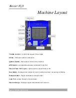
Page 18: ...on Switch Main power control to the machine APO Switch Activates Deactivates Automatic Pump Out Vacuum Tank Full Light Lights up when vacuum tank is full Hour Meter Displays total number of hours mach...

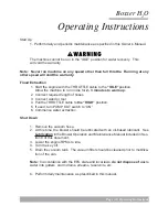
Page 19: ...required length of hoses 3 Connect wand or tool 4 Pull the THROTTLE cable to the HIGH position 5 If used turn PUMP OUT switch to ON 6 Commence water extraction Shut Down 1 Remove the vacuum hose 2 At...

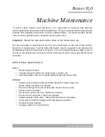
Page 20: ...efore the warranty is honored It is recommended that you affix a copy of the log on the vehicle door near your unit for convenience and to serve as a maintenance reminder OPERATIONAL MAINTENANCE DAILY...

Page 21: ...Check drive coupler for cracks or wear Replace as necessary Change oil in blower 500 HOURS Check coupler element between the engine and the blower replace as necessary OVERALL MACHINE MAINTENANCE Main...

Page 22: ...ck wand head for sharp edges that could tear carpet File down as needed Clean wand to maintain original appearance Wipe down vacuum hoses as needed Visually inspect hoses for cuts etc WEEKLY Wipe down...

Page 23: ...ion WEEKLY SERVICE DATE HOURS See Note 25 25 25 25 25 25 OIL change with filter BLOWER check oil level DRIVE SYSTEM tighten screws NUTS BOLTS check tightness VAC RELIEF VALVE inspect clean lube VACUUM...

Page 24: ...Page 5 1 Machine Assemblies and Parts List Boxxer H2 O Machine Assemblies and Parts Lists Figure 5 1 Machine Assembly Front View Left Side D 6800 Rev 3 1 2...

Page 25: ...5 2 Machine Assembly Front View Right Side D 6800 Rev Item Part Number Description Qty Machine Assembly Parts List 1 610 001 036 Assembly Frame Boxxer H2O Fig 5 3 5 5 1 2 610 050 033 Assembly Machine...

Page 26: ...Page 5 3 Machine Assemblies and Parts List Boxxer H2 O Figure 5 3 Frame Assembly Front View Left Side D 6801 Rev 2 5 4 16 16 1 3 10 10 19 20 6 12 11 21...

Page 27: ...chine Assemblies and Parts List Boxxer H2 O Figure 5 4 Frame Assembly Front View Right Side D 6801 Rev 7 9 9 8 8 8 15 13 14 14 13 15 15 14 13 10 10 11 12 6 6 HIDDEN HIDDENHIDDEN HIDDEN HIDDEN HIDDEN H...

Page 28: ...ate Machine Serial I D 1 8 000 033 053 Clamp 1 1 2 Cushion Loop 3 9 000 140 015 Rivet 1 8 x 1 4 Lg Pop 2 10 000 020 063 Bushing Snap 0 55 O D x 0 312 I D 4 11 000 143 013 Screw 5 16 18UNC x 1 00 Lg Gr...

Page 29: ...aMaster Corporation Page 5 6 Machine Assemblies and Parts List Boxxer H2 O Figure 5 5 Engine Assembly D 6802 Rev 10 9 7 7 25 10 11 13 24 12 11 10 26 19 22 21 4 5 6 16 18 15 1 3 8 17 7 14 20 23 21 27 2...

Page 30: ...8UNC Hex 2 Way Locking 6 12 000 033 117 Clamp 1 Cushion Loop w 7 16 Mount Hole 1 13 000 052 063 Bushing 14mm x 1 4 NPT Engine Oil Drain Adapter 1 14 000 068 221 Hose Engine Oil Drain 1 15 000 174 032...

Page 31: ...orporation Page 5 8 Machine Assemblies and Parts List Boxxer H2 O Figure 5 6 Blower Assembly D 6803 Rev 13 7 24 8 25 20 18 23 5 7 13 14 5 12 6 2 21 22 21 17 16 15 19 1 11 8 9 10 8 4 3 29 28 8 14 8 24...

Page 32: ...4 12 000 174 023 Washer 1 2 Lock 1 13 000 052 074 Nipple 3 8 NPT Hex 2 14 000 143 018 Screw 3 8 16UNC x 1 00 Lg Grade 8 7 15 000 001 115 Adapter Blower Flange To 3 M Slip Boxxer 427 1 16 000 174 019...

Page 33: ...HydraMaster Corporation Page 5 10 Machine Assemblies and Parts List Boxxer H2 O Figure 5 7 Dash Assembly D 6804 Rev 15 2 11 12 14 11 12 8 9 4 10 7 3 6 5 16 17 1 11 12 14 22 18 24 23 23 24...

Page 34: ...r Lubrication Port 1 10 000 084 011 Light Red Led Indicator Mini 1 11 000 174 001 Washer 10 Flat 13 12 000 174 014 Washer 10 Lock 13 13 000 143 134 Screw 10 24UNC x 1 00 Lg Hex Head 2 14 000 143 126 S...

Page 35: ...HydraMaster Corporation Page 5 12 Machine Assemblies and Parts List Boxxer H2 O Figure 5 8 Exhaust Assembly D 6805 Rev 12 11 4 13 6 12 11 3 13 17 16 15 8 7 10 9 2 13 5 13 14 11 17 16 18 1...

Page 36: ...Hose 3 I D x 3 Ply Silicone Bulk 1 7 000 057 177 Gasket Exhaust Donut 1 50 1 8 000 125 128 Tube 1 3 8 O D x 1 8 Wall x 7 8 Long 1 9 000 143 124 Screw 5 16 18UNC x 1 75 Lg Hex Head 2 10 000 094 081 Nut...

Page 37: ...6 2 4 3 4 3 Item Part Number Description Qty Machine Left Side Cover Assembly Parts List 1 000 041 417 Cover Left Side Machine Boxxer 427 1 2 000 105 313 Plate Hydramaster Name Roto Tank 1 3 000 174...

Page 38: ...t Figure 5 10 Machine Right Side Cover Assembly D 5762 Rev 5 6 6 5 1 2 3 4 3 4 1 000 041 419 Cover Right Side Machine Boxxer 427 1 2 000 105 313 Plate Hydramaster Name Roto Tank 1 3 000 174 001 Washer...

Page 39: ...Page 5 16 Machine Assemblies and Parts List Boxxer H2 O Figure 5 11 Recovery Tank Assembly D 6806 Rev 3 2 19 9 12 22 21 14 4 16 15 17 18 31 7 29 30 8 25 28 6 10 27 17 24 23 26 21 14 26 1 5 13 11 HIDDE...

Page 40: ...utton Head Allen 4 13 000 094 063 Nut 6 32UNC Nylock 4 14 000 143 001 Screw 1 4 20UNC x 0 75 Lg Hex Head 8 15 000 033 022 Clamp 1 2 Nylon Hose 1 16 000 057 178 Gasket Vacuum Relief Plate 1 17 000 143...

Page 41: ...0 057 015 Gasket 1 1 2 Bulkhead Fitting 2 4 000 052 219 Adapter 2 NPT x 2 F Slip 2 5 000 143 539 Screw 6 32UNC x 0 50 Lg Button Head Allen 4 6 000 086 008 Latch Bungie Strike 2 7 000 094 063 Nut 6 32U...

Page 42: ...ief Valve 1 2 000 027 032 Cap Vacuum Releif Valve 1 3 000 125 111 Pipe Vacuum Relief Spring Guide 1 4 000 105 067 Plate Vacuum Relief Valve Mounting 1 5 000 155 026 Spring Vacuum Relief 1 6 000 143 19...

Page 43: ...Corporation Page 5 20 Machine Assemblies and Parts List Boxxer H2 O Figure 5 14 Dura Flow APO Assembly D 5654 Rev C 19 18 19 20 21 22 23 24 20 25 1 9 10 5 8 3 8 2 7 6 16 17 16 17 13 4 14 12 15 17 16 7...

Page 44: ...k Banjo 100F 1 10 000 052 724 Fitting 1 NPT Cam Lock Banjo 100B 1 11 000 157 022 Switch Relay 1 12 000 012 011 Block 6 Post 1 13 000 094 027 Nut 10 24UNC Hex 1 14 000 143 532 Screw 6 32UNC x 5 8 Lg So...

Page 45: ...HydraMaster Corporation Page 5 22 Machine Assemblies and Parts List Boxxer H2 O To be Added...

Page 46: ...Page 5 23 Machine Assemblies and Parts List Boxxer H2 O To be Added...

Page 47: ...cuum inlet on top of the machine is open To protect the vacuum blower from overloading and damaging itself there is a vacuum relief system installed on the vacuum tank When the vacuum tank inlet is co...

Page 48: ...uid VACUUM TANK FILTER BAGS HydraMaster filter bags are designed to trap lint sand and dirt that would normally collect at the bottom of your vacuum tank The use of these bags if emptied at the end of...

Page 49: ...sket Make sure recovery tank drain valve is fully closed 2 2 Vacuum blower is turning too slowly Check engine RPM Adjust as necessary to 3000RPM 2 3 The vacuum gauge is defective Test gauge and replac...

Page 50: ...If unable to free up blower in this manner refer to qualified service technician 5 2 There is internal damage to the blower Refer to qualified service technician Miscellaneous Troubleshooting 1 0 Wate...

Page 51: ...so as to keep any necessary troubleshooting as easy as pos sible The entire electrical system operates on 12 volts DC which is provided by a battery Bat tery levels are sustained by a 16 amp alternato...

Page 52: ...HydraMaster Corporation Page 7 3 Electrical System Boxxer H2 O Figure 7 1 Wiring Schematic D 6838 Rev...

Page 53: ...HydraMaster Corporation Page 7 4 Electrical System Boxxer H2 O Figure 7 2 Wiring Diagram D 6837 Rev...

Page 54: ...ier 1 2 The stator winding is bad Check for AC voltage at the regulator rectifier The stator should be pro ducing an AC voltage of around 25 to 40 volts Check your Owner s manual for the exact voltage...

Page 55: ...the starter solenoid If there is 12 volts at the battery connection and at the key switch connection with the key in the start position but there is not 12 volts on the starter connection of the solen...

Page 56: ...p and the ground is good replace the pump 3 2 Recovery tank is full Empty the tank 3 3 Recovery tank float is defective Disconnect float If engine starts replace the float 3 4 The carb solenoid is mal...

Page 57: ...emove and inspect spark plugs Replace as necessary 5 2 A spark plug wire is loose at the spark plug or has been damaged Inspect wire Replace wire and coil as necessary 5 3 Low compression on one or bo...

Page 58: ...ssary 7 3 Excessive fuel to carburetor Insure that fuel pump is proper PSI rating A fuel pump with a psi rating in excess of that of the pump supplied with the machine could overpower the inlet valve...

Page 59: ...rs on the Unit D Unit Serial Number E Description of Malfunction 3 Once it has been determined which parts are needed to correct the problem with your machine make arrangements with your distributor t...

Page 60: ...mer Service Department 425 775 7275 8 a m to 5 p m Monday through Friday PST We shall always endeavor to be fair in our evaluation of your warranty claim and shall provide you with a complete analysis...

Page 61: ...orrect oil grade and viscosity as recommended in blower manual Failure to properly maintain blower safeguard systems such as waste tank filter screen vacuum safety relief valve and waste tank automati...

Page 62: ...distributors maintaining current account status An invoice will be sent to the distributor for the amount of the parts sent The customer s faulty parts must be returned for evaluation prior to the ex...

Reviews: