background image

Copyright© 2008

HYDRAMASTER®

 Corporation

Mukilteo, Washington

MAN-182-077-D

No part of this manual may be reproduced or used in any form or by any means (i.e. graphic, electronic, photocopying or
electronic retrieval systems) without the express written permission of the 

HYDRAMASTER

 Corporation.  All rights reserved.

Revised October 2008

11015 47th Avenue W, Mukilteo, WA  98275

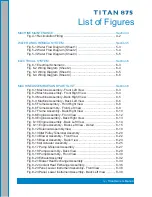
Summary of Contents for Titan 875

Page 1: ...this manual may be reproduced or used in any form or by any means i e graphic electronic photocopying or electronic retrieval systems without the express written permission of the HYDRAMASTER Corpora...

Page 2: ...se and Recover 2 3 Over Wetting 2 4 Streaking 2 4 SYSTEM OPERATION Section 3 Machine Specifications 3 2 Spare Parts List 3 3 Operating Instructions 3 4 Setting the Temperature 3 6 Machine Safeties 3 7...

Page 3: ...LIST Section 8 Machine Hose Routings 8 75 HOW TO ORDER PARTS Section 9 Warranty Parts Orders 9 2 Parts Orders 9 2 Emergencies 9 2 One Final Note 9 3 WARRANTYINFORMATION Section 10 Blower 10 2 High Pr...

Page 4: ...ront Right View 8 8 Fig 8 6 FrameAssembly Front Left View 8 9 Fig 8 7 Frame Assembly Back Right View 8 10 Fig 8 8 EngineAssembly Front View 8 12 Fig 8 9 EngineAssembly Back Right View 8 13 Fig 8 10 En...

Page 5: ...54 Fig 8 34 Inset Dash Assembly 8 56 Fig 8 35 Grill Dash Assembly 8 58 Fig 8 36 Electrical Panel Assembly 8 60 Fig 8 37 Cover CatalyticAssembly 8 62 Fig 8 38 Top Cover MachineAssembly 8 64 Fig 8 39 Le...

Page 6: ...ral Information 1 General Information This section contains the following helpful information Contact Information Warnings Cautions and Notices Responsibilities High Altitude Operation Local Water Pre...

Page 7: ...1 2 General Information Hours Monday Friday 7 00 am to 5 00 pm PACIFIC STANDARD TIME Telephone Numbers 425 775 7276 Parts 425 775 7275 Service 800 426 4225 Parts Service FAX Contact Information...

Page 8: ...ol indicates a situation which if not avoided could result in death or serious injury This symbol indicates a hazardous situation which if not avoided could result in dam age to the truck mount This s...

Page 9: ...protective equipment if a person is exposed to an average of 85 decibels over an eight hour period Check with local and state agencies concerning hearing conservation rules During the operation of th...

Page 10: ...e the risk of fire and explosion Serious injury or death may result During the operation of the truck mount the exhaust system will become extremely hot Keep all flammable materials away from the truc...

Page 11: ...or higher Using reading than 3 0 grains per gallon will cause scale to build up inside the truck mount water system Scale build up causes serious component dam age Test all water prior to use and use...

Page 12: ...rchase a heavy duty Group 24 battery for this truck mount This is normally available from the installation dealer Prior to dropping your van off at the distributor for the truck mount to be installed...

Page 13: ...ibility to verify that the equipment package does not exceed the vehicle capacity Ensure installation of a safe fuel tap system and through floor fittings as provided by HydraMaster Proper placement o...

Page 14: ...hut down the truck mount How to correctly clean with the truck mount Where and how often to check and change component oil levels Freezing damage and how to avoid it This includes explaining proper fr...

Page 15: ...minations is the output The fuel pressure manifold has three ports The side with the two ports is the return and the inlet the side with the single port is the output The dual port side has one connec...

Page 16: ...he outlet side of the pump failure to do so may cause the engine to run poorly It is important that the order of the fuel supply components are installed correctly failure to do so may cause the engin...

Page 17: ...he installation of a spray on bed liner in the vehicle prior to installation of machine This provides metal to cushion mounting rather than metal to metal and makes for an attractive van interior It i...

Page 18: ...OOR Although this location partly limits working access it does direct the noise away from the cleaning site Some cleaners in the colder areas prefer this location because it puts the weight over the...

Page 19: ...with the hardware sup plied A sudden or crash stop will cause the machine to rocket forward Protect your self and the machine SECURE IT Figure 1 4 Installation Using Tie down Cleats It is recommended...

Page 20: ...rtable propane tank inside of the truck or van It is dangerous and illegal in most states Transportation in a vehicle of any vented fuel container that presently holds or has ever held a flammable liq...

Page 21: ...e to altitude differences The engine electronic control system constantly monitors the barometric pressure and fuel mixture in the exhaust Using these two inputs the engine can compensate for any elev...

Page 22: ...ore info visit www systemsaver com You should always consider water from a well as hard water It is imperative that special precautions be taken with any truck mount operated in an area in which the w...

Page 23: ...he carpet cleaning trade and can produce only as a good a job as the person operating it HydraMaster strongly recommends attending an Institute of Inspection Cleaning and Restoration Certification IIC...

Page 24: ...tc HydraMaster s ClearWater Rinse has been formulated to protect vital components HydraMaster will not warranty parts that have been damaged from using acid products that have obviously caused failure...

Page 25: ...a with vacuum only to remove any excess moisture Olefin fiber is becoming more popular particularly in commercial installations The process mentioned above can leave excessive residual moisture becaus...

Page 26: ...drain valve left partially open 4 Obstructed cut or kinked vacuum hoses 5 Obstructed vacuum hoses while cleaning a heavily foam saturated carpet it is recommended to use a crystal type defoamer distri...

Page 27: ...tem Finally the chemical is injected into the pressur ized water stream and the heated solution is delivered to the cleaning tool The solution is recovered by the vacuum generated by the vacuum pump T...

Page 28: ...000 no heat Chemical System Last Step Chemical Injection Heating System Finned Tube Heat Exchanger Copper Tube and Shell High Pressure Hose 1 4 High Temperature Lined Vinyl Cover 150 ft 2 Vacuum Hose...

Page 29: ...1 157 040 Switch 20 Amp Rocker 2 157 022 Switch Relay 12V 2 052 050 Quick Connect 440 Male 2 052 051 Quick Connect 440 Female 2 052 052 Quick Connect 660 Male 1 052 053 Quick Connect 660 Female 1 046...

Page 30: ...tch to the HEAT MODE position 9 Set the HEAT SELECTOR valve to the desired position a Set to the COOL position for upholstery or single wand cleaning b Set to the HOT position for dual or triple wand...

Page 31: ...es and cleaning tool 3 Remove the vacuum hose 4 Lubricate the blower Cap off the inlet s to the vacuum tank Inject a small amount of light lubricating oil such as WD 40 Company s 3 in One or WD 40 int...

Page 32: ...uns to the job site c Reduced Heat Full Vacuum Single wand with short hose runs to the job site d Low Heat Reduced Vacuum Upholstery or any reduced solution flow cleaning 2 Maximum a Set the Heat Sele...

Page 33: ...ing after the condition is below the set point of the safety To reset the circuit you must first turn the pump clutch switch off and they back on again a Low Water Box b Pressure Switch c Low Pressure...

Page 34: ...og is provided in the Owner s Guide This log must be maintained and may be required to be furnished to HydraMaster before a warranty claim is honored It is recommended that the log be affixed to the v...

Page 35: ...ct the vacuum relief valve Clean and lubricate as necessary Clean the recovery tank thoroughly with pressure washer Check the pump drive blower belt drive and fan belt for wear and proper tension Tigh...

Page 36: ...cessive carbon buildup is visible Change the blower oil after first 100 hours of use 500 Hours Change the blower oil Change the high pressure pump oil Check the engine valve clearance intake and exhau...

Page 37: ...hly with a damp cloth Wipe down the vacuum and high pressure hoses as needed Inspect and clean the vacuum slot on the cleaning wand Check the wand head for sharp edges that could tear carpet File down...

Page 38: ...t be changed every 150 hours or every three months whichever occurs first The oil and filter should be changed more often if the engine is operating in dusty or extremely dirty areas or during cold we...

Page 39: ...hard starting spark knock and run on Installing new spark plugs regularly is one of the best ways to keep your engine at peak performance Cooling System Coolant Level Check the coolant level of the r...

Page 40: ...ler neck Start the engine and run in the low RPM position pump clutch off and no vacuum load Allow the engine coolant to heat up and open the thermostat several times As all the air is removed from th...

Page 41: ...unning in high ambient temperatures High Pressure Pump Maintenance If the oil becomes discolored or contaminated one of the oil seals may be damaged Do not operate the pump if the crankcase oil has be...

Page 42: ...The next few pages explain how to disassemble and inspect all user serviceable parts of the pump Do not disassemble the pump unless you are a skilled mechanic For assistance contact HydraMaster or you...

Page 43: ...4 10 Machine Maintenance...

Page 44: ...4 11 Machine Maintenance...

Page 45: ...4 12 Machine Maintenance...

Page 46: ...4 13 Machine Maintenance...

Page 47: ...4 14 Machine Maintenance...

Page 48: ...4 15 Machine Maintenance...

Page 49: ...4 16 Machine Maintenance...

Page 50: ...4 17 Machine Maintenance...

Page 51: ...4 18 Machine Maintenance...

Page 52: ...4 19 Machine Maintenance...

Page 53: ...4 20 Machine Maintenance...

Page 54: ...4 21 Machine Maintenance...

Page 55: ...4 22 Machine Maintenance...

Page 56: ...4 23 Machine Maintenance...

Page 57: ...4 24 Machine Maintenance...

Page 58: ...4 25 Machine Maintenance...

Page 59: ...4 26 Machine Maintenance...

Page 60: ...for test purposes with the inlet to the blower open to the atmosphere Foam passing through the blower can lead to serious problems with the truckmount It is important to keep the vacuum tank free of...

Page 61: ...art no 078 058 start with an empty water box Fill a third of the water box with TM DeScaler Follow the recommendations on the TM DeScaler label for proportions Verify that the float is not lying horiz...

Page 62: ...the outgoing solution fitting on the front of the machine Attach the opposite end to the recirculation fitting If more sections of hose are to be freeze guarded attach those inline 3 Start the truckmo...

Page 63: ...n freeze guarded to the truckmount 2 Attach the incoming water source to the front of the truckmount 3 Start the truckmount 4 Spray the solution through the hoses and wands into a sealable container u...

Page 64: ...1 Water and Chemical System 5 Water and Chemical System This section describes the water and chemical systems in the following areas Water and Chemical Flow Operation Water and Chemical Flow Diagrams...

Page 65: ...eat control system that also acts as a high temperature shutdown switch There is one orifice located in the manifold This is referred to as a recirculation orifice and allows a small amount of high pr...

Page 66: ...5 3 Water and Chemical System Figure 5 1 Flow Diagram D 6701 Rev A Sheet 1...

Page 67: ...5 4 Water and Chemical System Figure 5 2 Flow Diagram D 6701 Rev A Sheet 2...

Page 68: ...5 5 Water and Chemical System Figure 5 3 Flow Diagram D 6701 Rev A Sheet 3...

Page 69: ...6 1 Electrical System 6 Electrical System This section describes how the electrical system functions in the following manner Electrical System Information Electrical Schematic Wiring Diagram...

Page 70: ...DC which is provided by the battery Battery levels are maintained by a 70Amp generator mounted on the engine NOTE When a new battery is installed check that it is properly charged before installa tio...

Page 71: ...6 3 Electrical System Figure 6 1 Electrical Schematic D 6700 Rev B...

Page 72: ...6 4 Electrical System Figure 6 2 Wiring Diagram D 6699 Rev B Sheet 2...

Page 73: ...6 5 Electrical System Figure 6 3 Wiring Diagram D 6699 Rev B Sheet 3...

Page 74: ...6 6 Electrical System Figure 6 4 Wiring Diagram D 6699 Rev B Sheet 4...

Page 75: ...7 1 Troubleshootiing 7 Troubleshooting This section describes the standard troubleshooting procedures in the following areas Heating System Chemical System Engine High Pressure System Vacuum System...

Page 76: ...re controller and sensor Possible Cause Solution Temperature controlknob is turned down Inspect theknob Adjust if necessary Thedumb solenoid is faulty Inspect thesolenoid and test for functionality If...

Page 77: ...y Possible Cause Solution Air is in the lines Check that allfittings and connections are tight and in good condition Repair or replace as necessary The filter screen in the chemicaljug is partially ob...

Page 78: ...Test to see if there is power to the motor with the ignition in Start position Refer to the ElectricalSection None of the above Refer to a qualified service technician for further troubleshooting Pos...

Page 79: ...her troubleshooting Possible Cause Solution Open allthe van doors Install a roof vent in the van Remove any dividers or other objects impeding airflow around the truck mount Low oil level Check the le...

Page 80: ...ecessary Refer to the Machine Assemblies Parts List Section The primary orifice is worn Measure the orifice size and replace as necessary Correct size is 033 in Possible Cause Solution The pump belt i...

Page 81: ...pect the supply systemfromthe source through the incoming quick connect The float valve in the water boxis faulty Disassemble and inspect the valve Repair or replace as necessary Possible Cause Soluti...

Page 82: ...umgauge is defective Test the gauge and replace if necessary Possible Cause Solution The filter in recovery tank is clogged Remove and clean or replace as necessary The hose fromrecovery tank to the v...

Page 83: ...drain the tank Inspect the high level shutoff switch for proper operation Clean or replace the switch as necessary If foam is in recovery tank use defoamer on the carpet being cleaned Condensation in...

Page 84: ...sembly Idler Pulley TensionerAssembly BlowerAssembly AirActuatorAssembly Pump SilencerAssembly Pump Assembly ExhaustAssembly Blower Heat ExchangerAssembly Coolant Heat Exchanger Assembly Panel Lower I...

Page 85: ...embly Cover Catalytic Assembly Top Cover MachineAssembly Left Side Cover Machine Assembly Right Side Cover Machine Assembly 100 Gallon Universal RecoveryTank Assembly Cover 100 Gallon Universal Recove...

Page 86: ...8 3 Machine Assemblies and Parts List Figure 8 1 Machine Assembly Front Left View D 6600 Rev...

Page 87: ...8 4 Machine Assemblies and Parts List Figure 8 2 Machine Assembly Front Right View D 6600 Rev...

Page 88: ...8 5 Machine Assemblies and Parts List Figure 8 3 Machine Assembly Back Right View D 6600 Rev...

Page 89: ...8 6 Machine Assemblies and Parts List Figure 8 4 Machine Assembly Back Left View D 6600 Rev...

Page 90: ...ne Assembly Parts List 1 Fig 8 5 8 7 Assembly Frame 1 2 000 041 454 Cover Brow Machine 1 3 Fig 8 40 Assembly Machine Right Side Cover 1 4 000 155 053 Spring 1 4 Belleville Washer 2 5 000 143 126 Screw...

Page 91: ...8 8 Machine Assemblies and Parts List Figure 8 5 Frame Assembly Front Right View D 6601 Rev A...

Page 92: ...8 9 Machine Assemblies and Parts List Figure 8 6 Frame Assembly Front Left View D 6601 Rev A 1...

Page 93: ...8 10 Machine Assemblies and Parts List Figure 8 7 Frame Assembly Back Right View D 6601 Rev A...

Page 94: ...Panel Lower Instrument 1 10 Fig 8 36 Assembly Electrical Panel 1 11 Fig 8 31 Assembly Poly Water Box 8G 1 12 000 055 187 Frame Titan Weldment 1 13 Fig 8 37 Assembly Cover Catalytic 1 14 000 154 157 S...

Page 95: ...8 12 Machine Assemblies and Parts List Figure 8 8 Engine Assembly Front View D 6602 Rev F...

Page 96: ...8 13 Machine Assemblies and Parts List Figure 8 9 Engine Assembly Back Right View D 6602 Rev F...

Page 97: ...8 14 Machine Assemblies and Parts List Figure 8 10 Engine Assembly Back Left View D 6602 Rev F...

Page 98: ...8 15 Machine Assemblies and Parts List Figure 8 11 Engine Assembly Back Left View Detail D 6602 Rev F...

Page 99: ...Cushion Loop w 7 16 Mounting Hole 8 14 000 033 057 Clamp 1 Cushion Loop 2 15 000 033 117 Clamp 1 Cushion Loop w 7 16 Mount Hole 1 16 000 047 027 Engine 1 6L Gm 1 17 000 052 063 Bushing 14mm x 1 4 NPT...

Page 100: ...10 Flat 4 37 000 174 004 Washer 5 16 Flat 1 38 000 174 005 Washer 3 8 Flat 8 39 000 174 006 Washer 7 16 Flat 11 40 000 174 105 Washer 1 1 16 I D SelfAligning Spherical 2 Pc Set 3 41 000 174 007 Washer...

Page 101: ...8 18 Machine Assemblies and Parts List Figure 8 12 Solenoid Assembly C 6645 Rev A...

Page 102: ...0 015 945 Bracket Solenoid Mount 1 2 000 012 001 Block 4 Lead ElectricalTerminal 1 3 000 052 106 Insert 1 8 NPT x 5 32 Barb x 90 4 4 000 106 014 Plug Vent 2 5 000 143 047 Screw 6 32 UNC x 875 Lg PH Ph...

Page 103: ...8 20 Machine Assemblies and Parts List Figure 8 13 Idler Pulley Tensioner Assembly C 6660 Rev...

Page 104: ...Bracket Idler PulleyTensioner 1 2 000 154 015 Spacer Idler Pulley 1 3 000 150 011 Shaft Idler Pulley 1 4 000 109 117 Pulley Quad Groove 3VX Idler 1 5 000 094 105 Nut 3 4 16UNF Hex Zinc Plated 1 6 000...

Page 105: ...8 22 Machine Assemblies and Parts List Figure 8 14 Blower Assembly Front View D 6603 Rev A...

Page 106: ...8 23 Machine Assemblies and Parts List Figure 8 15 Blower Assembly Back View D 6603 Rev A...

Page 107: ...116 Clamp 1 1 2 Cushion Loop w 7 16 Mounting Hole 1 9 000 033 117 Clamp 1 Cushion Loop w 7 16 Mount Hole 2 10 000 052 083 Elbow 3 8 NPT Street x 45 2 11 000 052 293 Insert 23 1 8 NPT x 3 16 Barb 2 12...

Page 108: ...8 25 Machine Assemblies and Parts List Figure 8 16 AirActuator Assembly C 6608 Rev...

Page 109: ...Air Cylinder Mount Inner 1 3 000 015 953 Bracket Actuator Mount 1 4 000 015 954 Bracket Actuator Extension 1 5 000 052 550 Elbow 1 8 NPTx 3 16 Barb 2 6 000 094 092 Nut 7 16 20UNF Hex Jam 1 7 000 143 0...

Page 110: ...8 27 Machine Assemblies and Parts List Figure 8 17 Pump Silencer Assembly D 6604 Rev A...

Page 111: ...ection Weldment 1 2 Fig 8 18 8 19 Assembly Pump 1 3 000 143 017 Screw 3 8 16UNC x 0 75 Lg Hex Head Grd 8 6 4 000 174 005 Washer 3 8 Flat 7 5 000 143 024 Screw 3 8 16UNC x 5 Lg Hex Head Tap 1 6 000 143...

Page 112: ...8 29 Machine Assemblies and Parts List Figure 8 18 Pump Assembly Back View D 6618 Rev C...

Page 113: ...8 30 Machine Assemblies and Parts List Figure 8 19 Pump Assembly Front View D 6618 Rev C...

Page 114: ...Hose 17 Lg Pump Drain 1 14 000 094 071 Nut 1 4 20UNC Nylock 4 15 000 111 183 Pump General 1 16 000 111 184 Pump GP Chemical 1 17 000 143 126 Screw 10 24UNC x 0 50 Lg Hex Head 4 18 000 143 185 Screw 8m...

Page 115: ...8 32 Machine Assemblies and Parts List Figure 8 20 Exhaust Assembly D 6607 Rev A...

Page 116: ...d Flange Donut Seat 1 11 000 001 143 Adapter Exhaust 7 5 w Custom Fixed Flange Donut Seat 1 12 000 093 110 Catalytic Weldment 1 13 Sensor O2 GM 1 6LEngine 1 14 000 094 012 Nut 5 16 18 UNC Hex 4 15 000...

Page 117: ...8 34 Machine Assemblies and Parts List Figure 8 21 Blower Heat Exchanger Assembly D 6605 Rev E 5 5 29 5 21 7 0 1 1 7 6 9...

Page 118: ...icone 2 10 000 033 015 Clamp 4 Hose 4 11 000 038 073 Core Heat Exchanger 8 x 8 1 12 000 068 778 Hose 4 I D x 3 Ply Silicone 1 13 000 068 778 Hose 4 I D x 3 Ply Silicone 1 14 000 143 333 Screw 1 4 20UN...

Page 119: ...8 36 Machine Assemblies and Parts List Figure 8 22 Coolant Heat Exchanger Assembly D 6606 Rev B...

Page 120: ...000 033 020 Clamp Size 16 Hose 4 7 000 038 043 Heat Exchanger Water To Water 1 8 000 052 061 Bushing 3 8 NPT x 1 4 FPT 1 9 000 052 447 Tee 3 8 Male Branch 1 10 000 052 131 Elbow 1 NPTx 1 Barb Glass F...

Page 121: ...8 38 Machine Assemblies and Parts List Figure 8 23 Panel Lower Instrument Assembly Front View D 6612 Rev B...

Page 122: ...8 39 Machine Assemblies and Parts List Figure 8 24 Panel Lower Instrument Assembly Back Left View D 6612 Rev B...

Page 123: ...8 40 Machine Assemblies and Parts List Figure 8 25 Panel Lower Instrument Assembly Back Right View D 6612 Rev B...

Page 124: ...lbow 1 4 FPT x FPT 1 14 000 052 089 Elbow 1 8 NPT Female 2 15 000 052 096 Insert F23 1 8 FPT x 3 16 Barb 1 16 000 052 099 Insert 26 1 8 NPT x 3 8 Barb 3 17 000 052 104 Insert 66 3 8 NPT x 3 8 Barb 1 1...

Page 125: ...50 Lg Hex Head 10 38 000 143 327 Screw 10 32 UNF x 0 50 Lg Hex Head 2 39 000 143 542 Screw 1 4 28UNF x 0 50 Lg Hex Head 2 40 000 155 053 Spring 1 4 Belleville Washer 2 41 000 169 0171 Valve 3 Way Ball...

Page 126: ...8 43 Machine Assemblies and Parts List Figure 8 26 PSI Regulator Valve 0 3200 PSI Assembly C 6615 Rev A...

Page 127: ...Tee 1 4 NPT Branch M F F 1 7 000 052 102 Insert 46 1 4 NPT x 3 8 Barb 1 8 000 052 117 Insert 48 1 4 NPT x 1 2 Barb 1 9 000 052 532 Elbow 1 4 SAE x 1 4 NPT 1 10 000 052 587 Compression 3 16 x 1 4 NPT...

Page 128: ...8 45 Machine Assemblies and Parts List Figure 8 27 Orifice Manifold Assembly C 6616 Rev A...

Page 129: ...49 016 Filter 1 4 NPT Replacement Y 1 5 000 052 061 Bushing 3 8 NPT x 1 4 FPT 1 6 000 052 086 Elbow 3 8 NPTStreet 1 7 000 052 527 Nipple 1 4 SAE x 1 4 NPT 1 8 000 052 587 Compression 3 16 x 1 4 NPT Th...

Page 130: ...8 47 Machine Assemblies and Parts List Figure 8 28 Hi Pressure Out Manifold Assembly C 6646 Rev B...

Page 131: ...052 051 Quick Connect 440 Female w EPDM O Ring 3 3 000 052 071 Nipple 1 4 NPT Hex 3 4 000 052 074 Nipple 3 8 NPT Hex 1 5 000 052 086 Elbow 3 8 NPTStreet 1 6 000 106 008 Plug 3 8 NPTAllen Head 1 7 000...

Page 132: ...v B Item Part Number Description Qty 3 Way Valve Assembly Parts List 1 000 052 751 Elbow 3 8 JIC x 1 4 NPT 2 2 000 169 213 Valve 3 Way 1 4 FPT 1 3 000 052 533 Nipple 3 8 JIC x 1 4 NPT 2 4 000 052 090...

Page 133: ...Qty 2 Way Valve Assembly Parts List Figure 8 30 2 Way Valve Assembly B 6644 Rev C 1 000 169 214 Valve 2 Way Chem Pump 1 4 FPT S S 1 2 000 052 751 Elbow 3 8 JIC x 1 4 NPT 1 3 000 052 533 Nipple 3 8 JI...

Page 134: ...8 51 Machine Assemblies and Parts List Figure 8 31 Poly Water Box 8G Assembly D 6619 Rev A...

Page 135: ...x 3 8 Hose Barb 1 13 000 052 660 Bulkhead 3 8 FPT x 3 8 FPT 1 14 000 052 728 Bulkhead 1 2 FPT x 3 8 FPT 1 15 000 052 754 Insert F816 1 2 FPT x 1 Barb 1 16 000 057 052 Gasket 1 Garden Hose 1 17 000 068...

Page 136: ...ly B 6554 Rev Item Part Number Description Qty Diffuser Assembly Parts List 1 000 052 074 Nipple 3 8 NPT Hex 1 2 000 033 131 Clamp Diffuser 1 3 000 125 222 Tube Diffuser 1 4 000 027 115 Cap 2 Pvc Modi...

Page 137: ...8 54 Machine Assemblies and Parts List Figure 8 33 Upper Dash Assembly C 6610 Rev A...

Page 138: ...escription Qty Upper Dash Assembly Parts List 1 000 100 164 Panel Dash 1 2 Fig 8 34 Assembly Inset Dash 1 3 Fig 8 35 Assembly Grill 1 4 000 174 001 Washer 10 Flat 11 5 000 143 126 Screw 10 24UNC x 0 5...

Page 139: ...8 56 Machine Assemblies and Parts List Figure 8 34 Inset Dash Assembly D 6611 Rev A...

Page 140: ...ure 1 5 000 074 017 Gauge 0 30 Hg Vac 2 1 2 HydraMaster Face 1 6 000 074 018 Meter Rectangular w o Bezel 1 7 000 084 019 Light Blue LED Strip 1 8 000 149 551 Thermostat Potentiometer Dual Controller 1...

Page 141: ...8 58 Machine Assemblies and Parts List Figure 8 35 GrillAssembly C 6727 Rev A...

Page 142: ...ist Item Part Number Description Qty Grill Assembly Parts List 1 000 100 172 Panel Grill 1 2 000 100 173 Panel Logo Grill 1 3 000 100 174 Panel Backing Plate Grill 1 4 000 094 058 Nut 10 32UNF Nylock...

Page 143: ...8 36 Electrical PanelAssembly D 6617 Rev C Item Part Number Description Qty Electrical PanelAssembly Parts List 1 000 100 137 Panel Electrical Control 1 2 000 041 418 Cover Electrical Control Panel 1...

Page 144: ...cator Mini 1 17 000 094 003 Nut 10 32UNF Hex 2 18 000 094 034 Nut 10 24UNC Nylock s s 6 19 000 094 058 Nut 10 32UNF Nylock s s 2 20 000 094 108 Nut 10 32UNF Wing 2 21 000 135 004 Diode Plug In 3 22 00...

Page 145: ...8 62 Machine Assemblies and Parts List Figure 8 37 Cover Catalytic Assembly D 6730 Rev...

Page 146: ...1 458 Cover Side Catalytic 1 5 000 108 146 Protector CAT Cover 1 6 000 057 214 Gasket CAT Heat Shield 2 7 000 001 132 Adapter TankTo 3 0 Blower Hose 1 8 000 033 013 Clamp 48 Hose 3 1 9 000 068 398 Hos...

Page 147: ...8 64 Machine Assemblies and Parts List Figure 8 38 Top Cover Machine Assembly D 6609 Rev B...

Page 148: ...15 943 Bracket Air Cleaner 1 6 Air Cleaner Engine Comes w engine 1 7 000 094 038 Nut 5 16 18UNC Nylock 2 8 000 143 012 Screw 5 16 18UNC x 3 4 Lg 2 9 000 143 126 Screw 10 24UNC x 0 50 Lg Hex Head 10 10...

Page 149: ...er Machine Assembly C 6613 Rev Item Part Number Description Qty Left Side Cover Machine Assembly Parts List 1 000 041 449 Cover Left Side Machine 1 2 000 089 003 Magnet Treadmaster 4 3 000 094 034 Nut...

Page 150: ...on Qty Right Side Cover Machine Assembly Parts List Figure 8 40 Right Side Cover Machine Assembly C 6614 Rev 1 000 041 450 Cover Right Side Machine 1 2 000 089 003 Magnet Treadmaster 4 3 000 094 034 N...

Page 151: ...8 68 Machine Assemblies and Parts List Figure 8 41 100 Gallon Universal Recovery Tank Assembly D 6787...

Page 152: ...23 Clamp 3 4 Nylon Hose 2 12 000 094 113 Nut 1 4 20UNC Neoprene Wellnut 4 13 000 174 060 Washer 1 4 Rubber Backed 4 14 000 143 002 Screw 1 4 20UNC X 1 00 Lg Hex Head 12 15 000 106 049 Plug 1 NptAllen...

Page 153: ...ull Port Ball 1 37 SEE NOTES Label Maintenance Lube Schedule 1 100 Gallon Universal Recovery Tank Assembly Parts List Cover 100 Gallon Universal Recovery Tank Assembly Parts List Item Part Number Desc...

Page 154: ...k Assembly Parts List Item Part Number Description Qty 11 000 094 063 Nut 6 32UNC Nylock 4 12 000 086 008 Latch Bungee Catch 2 13 000 174 003 Washer 1 4 Flat 2 14 000 143 002 Screw 1 4 20UNC X 1 00 Lg...

Page 155: ...3 000 125 111 Pipe Vacuum Relief Spring Guide 1 4 000 105 332 Plate Vacuum Relief Valve Mounting Universal RecoveryT 1 5 000 155 026 Spring Vacuum Relief 1 6 000 143 198 Screw 3 8 16UNC x 4 Lg Hex Hea...

Page 156: ...8 73 Machine Assemblies and Parts List Figure 8 44 Dura Flow APOAssembly D 5654 Rev E...

Page 157: ...000 061 131 Knob Handle RDM 2 9 000 052 723 Fitting 1 NPT Cam Lock Banjo 100F 1 10 000 052 724 Fitting 1 NPT Cam Lock Banjo 100B 1 11 000 157 022 Switch Relay 1 12 000 012 011 Block 6 Post 1 13 000 09...

Page 158: ...olant HX Back 068 787 18 3 8 Teflon 3 Way Valve Out Bottom Blower HX Front 068 788 27 5 3 8 Teflon Orifice Manifold Blower HX Back 068 326 52 3 8 Clear Braid Chemical Jug Flow Meter In Bottom 068 806...

Page 159: ...r Parts This section describes how to obtain a proper diagnosis of any malfunctions and how to order warranty replacement parts or repairs as outlined in the following areas Warranty Parts Orders Part...

Page 160: ...ch parts are needed to correct the problem with your truckmount make arrangements with your distributor to either perform the repairs or ship the parts to you PARTS ORDERS Call your local distributor...

Page 161: ...nt 425 775 7275 7 a m to 5 p m Monday through Friday PST We shall always endeavor to be fair in our evaluation of your warranty claim and shall provide you with a complete analysis of our findings Hyd...

Page 162: ...s which might occur between truck mount owners and manufac turer Such causes as listed in this section shall constituteabuse or neglect The following areas are covered in this section Blower High Pres...

Page 163: ...el as recommended in the pump manual Failure to change the oil in the pump at recommended intervals Failure to protect the pump against freezing Failure to maintain the pump protection shut off system...

Page 164: ...mal wear and tear from everyday use Cleaning Wand Failure to protect against freezing Obvious physical abuse of the wand Water Heating System Over pressurization of the system recommended maximum work...

Page 165: ...presentative IMPORTANT HydraMaster s warranty policy provides replacement parts without charge for sixty 60 days to distributors maintaining current account status An invoice will be sent to the distr...

Page 166: ...changed the shape of steam cleaning Our hoses and tanks are of the finest quality construction HydraMaster chemicals have been specially prepared not only to give you exceptional cleaning but also to...

Page 167: ...lacement Air Gas Blowers 21 Grease Lubrication Air Service Plus 22 Splash Lubrication Air Service SL 23 Splash Lubrication Gas Service GT Plus 21 Series SL GT 22 23 Series LEADING THE SEARCH FOR NEW S...

Page 168: ...parts of the blower and driving equipment can produce serious physical injuries Do not reach into any opening in the blower while it is operating or while subject to accidental starting Cover externa...

Page 169: ...E 8 RECOMMENDED SHUTDOWN PROCEDURE TO MINIMIZE RISK OF FREEZING OR CORROSION 8 TROUBLESHOOTING 9 Troubleshooting FAQ 10 DISASSEMBLY INSPECTION 10 BLOWER ASSEMBLY 11 MECHANICAL SEAL INSTALLATION 11 LUB...

Page 170: ...dentification on any replacement part orders or if you require service or application assistance FLOW DIRECTION BY ROTATION Refer to the illustrations below before installing inlet and discharge pipin...

Page 171: ...l you are positive that it has been properly and fully lubricated See Lubrication Section on page 6 PIPING Inlet and outlet connections on all blowers are large enough to handle maximum volume with mi...

Page 172: ...3006 3 4 ounces 100 mL 2 5 ounces 75 mL 6 0 ounces 180 mL 4 0 ounces 120 mL 4002 4007 5 8 ounces 170 mL 4 7 ounces 140 mL 8 5 ounces 250 mL 6 4 ounces 190 mL 5003 5009 7 1 ounces 210 mL 5 4 ounces 160...

Page 173: ...Grease Fitting Relief Fitting Grease Fitting Relief Fitting LEFT DRIVE RIGHT DRIVE CAUTION Most Competitor blowers are shipped from the factory in a left hand drive vertical flow configuration If dri...

Page 174: ...or drive components Bump the unit with the motor a few times to check rotation and to be certain it turns freely and smoothly Start the unit and operate it for 30 minutes at no load During this time f...

Page 175: ...due to improper mounting or pipe strains Check mounting alignment and relieve pipe strains Excessive pressure differential Reduce to manufacturer s recommended pressure Examine relief valve and reset...

Page 176: ...y where these parts are exposed If at any point of inspection repair or replacement is deemed necessary appropriate instruction will be given to achieve these repairs or replacements NOTE Items in bra...

Page 177: ...orough cleaning of the seal and bearing bores of both end plates apply a thin coat of sealant on the outside diameter of the new seals and press them into the end plate using a tool that will bear on...

Page 178: ...Lubricate shafts and bearings Install the ball bearing 12 on the driven rotor and the roller bearing 11 on the input shaft Apply a bead of a good quality RTV silicone sealant to the inner surface of t...

Page 179: ...and BB reading 003 08 mm by removing 006 15 mm shims the readings will change one half the amount removed or 003 08 mm AA should then read 006 15 mm and BB should read 006 15 mm The final reading shou...

Page 180: ...04 004 007 10 18 003 005 07 13 008 011 20 28 005 009 13 23 002 004 05 10 003 006 08 15 3002 004 007 10 18 003 005 07 13 008 012 20 30 006 012 15 30 002 005 05 13 004 007 10 18 3003 005 008 13 20 003 0...

Page 181: ...to 32 F 18 to 0 C PneuLube FG ISO 100 CONSULT FACTORY 32 to 90 F 0 to 32 C 90 to 120 F 32 to 50 C RECOMMENDED SYNTHETIC BASED LUBRICANTS AMBIENT TEMPERATURE TUTHILL EXXONMOBIL SHELL 0 to 32 F 18 to 0...

Page 182: ...crew Hex Head 2 12 Bearing 1 30 Timing Shims 10 13 Bearing 2 31 Gear Timing Key 2 15 Screw Hex Head 16 42 Alum Nameplate Kit 1 16 Screw Hex Head 8 43 Dr Screw 2 17 Screw Hex Head 4 47 Teflon Vent Inse...

Page 183: ...er 2 10 Drive Cover 1 29 Screw Socket Head 3 11 Roller Bearing 1 30 Timing Shims 1 12 Bearing 1 31 Timing Gear Key 2 13 Bearing 2 44 Dowel Pin 1 15 Screw Hex Head 16 45 Slinger 1 16 Screw Hex Head 16...

Page 184: ...605 005 2 00 005 6 25 005 5 50 005 MODEL A B C D E F 2000 1 560 001 1 24 005 1 04 005 70 005 1 10 005 4 00 005 3000 2 035 001 1 74 005 1 54 005 1 015 005 1 415 005 4 37 005 4000 2 425 001 1 865 005 1...

Page 185: ...2 627 1 420 1 417 1 397 0 750 2 578 2 438 2 927 2 802 2 230 1 383 2 090 5 000 5 500 2 000 0 1745 0 5 2 6745 2 434 0 75 1 722 1 735 3 0695 0 220 2 8495 1 738 3 COMPETITOR GT SEAL INSTALLATION TOOLS FOR...

Page 186: ...make any manual adjustments found necessary Turn off and lock out power Remove the fasteners from the belt guard if equipped Remove the belt guard Check and adjust the belt tension as necessary It sh...

Page 187: ...21...

Page 188: ...Unless done with prior written consent of Seller any repairs alterations or disassembly of Seller s equipment shall void warranty Installation and transportation costs are not included and defective...

Page 189: ...ation and Maintenance Manual Industrial Gasoline Alternative Fueled Engines 1 6L 3 0L 4 3L 5 0L 5 7L and 8 1L Engines A GM Powertrain Product by Power Solutions Inc Wood Dale IL 60191 36100007B REV 3...

Page 190: ...ems 6 PSI Fuel Injection Gasoline 6 PSI Fuel Injection Dual Fuel 6 Stopping the Engine 7 Fuel Recommendations 7 Fuel Quality 7 Anti Knock Index Octane Rating 7 Gasohol and Alcohol Gasoline Fuel 8 Spar...

Page 191: ...ming Procedures 15 Maintenance Schedule 16 Capacity Chart 16 Filter Chart 17 Fuel System Chart 18 Governor Chart 18 General Speci cations 19 Spark Plug Wire Routing 3 0L 20 Spark Plug Wire Routing 4 3...

Page 192: ...as standard or optional All the equipment described in this manual may not be found on your engine or power unit Please pay special attention to the NOTES CAUTIONS and WARNINGS WARNINGS remind you to...

Page 193: ...obtained usually 2 to 5 seconds The engine will continue to run when the button is released CAUTION If the engine does not continue to run when the button is released it will be necessary to check th...

Page 194: ...function of this panel Oil Pressure Reading The oil pressure reading shows the engine lubrication system pressure in pounds per square inch psi and should be checked frequently to ensure that the syst...

Page 195: ...n 30 seconds at a time An interval of at least 1 minute should be observed between cranking periods to protect the starter from overheating LPG or NG Fuel Systems Turn on the gas supply to the engine...

Page 196: ...Prevent gum formation or other deterioration during storage Protect fuel tank and other fuel system components from corrosion or degradation Provide the correct seasonally and geographically adjusted...

Page 197: ...ems such as hard starting spark knock and run on Installing new spark plugs regularly is one of the best ways to keep your engine at peak performance Power Loss at Higher Elevations All engines will e...

Page 198: ...oil level should be checked daily It is recommended that the oil be checked just before the engine is started for the rst time for that day The oil level should be between the Add and the Full marks o...

Page 199: ...t temperatures are consistently below 0 degrees F SAE 5W 30 oil can be used Synthetic oils are not recommended for industrial or stationary engines Oil Filter The PSI GM Powertrain engines use an AC D...

Page 200: ...n the coolant level at to 1 inches below the ller neck seat of the radiator when the coolant is cold When ever coolant level checks are made inspect the condition of the radiator cap rubber seal Make...

Page 201: ...at the proper tension This belt should be checked routinely for cracks or checking on the groove side of the belt If cracks or check ing are apparent the belt must be changed V Type Belt V Type belts...

Page 202: ...lugs should be replaced at the recommended intervals described in the Maintenance Schedule Use only the recommended spark plug or an equivalent as described in the General Speci cations Spark plug gap...

Page 203: ...engine crankcase and re ll with recommended oil Change the oil lter Disconnect and remove the battery Clean exterior surface of the engine If the engine is equipped with an automotive type clutch or P...

Page 204: ...f the 4 3L 5 7L and 7 4L engines 5 Check and adjust the distributor as necessary viewing the timing mark on the crankshaft pulley in relation to the pointer on the engine timing case On some engines t...

Page 205: ...Cap Rotor X Replace Spark Plug Wires Replace Spark Plug Wires Replace Spark Plug Wires Replace Spark Plug Wires X Fuel System Maintenance Fuel System Maintenance Fuel System Maintenance Fuel System Ma...

Page 206: ...qts 8 qts Oil Capacity With Filter Oil Capacity With Filter Oil Capacity With Filter Oil Capacity Without Filter Oil Capacity With Filter Oil Capacity Without Filter Oil Capacity Without Filter Oil C...

Page 207: ...o LPG PSI EControls Impco LPG PSI ECotnrols Impco Dual Fuel PSI EControls Impco LPG x x x PSI Woodward Stationary PSI Woodward Stationary PSI ECotnrols Impco Dual Fuel PSI Woodward Stationary PSI ECot...

Page 208: ...4 7L PF 25 or Equivalent 5 qts 4 7L 5 qts 4 7L PF 25 or Equivalent 5 qts 4 7L PF 47 PF 52 or Equivalent PF 47 PF 52 or Equivalent 5 qts 4 7L PF 47 PF 52 or Equivalent 5 qts 4 7L 5 qts 4 7L PF 47 PF 5...

Page 209: ...20 PSI Operators Manual 3 0L Engine Spark Plug Wire Routing...

Page 210: ...PSI Operators Manual 21 4 3L Engine Spark Plug Wire Routing...

Page 211: ...22 PSI Operators Manual 5 0L 5 7L Engine Spark Plug Wire Routing...

Reviews: