


4
PSI Operators Manual
Parts and Service
Replacement parts can be obtained from Power Solutions, Inc. by calling the Service Parts Department at 888-
331-5769. The engine model and serial number will be required when seeking information and/or ordering
parts.
Service and technical support for GM Powertrain engines supplied by Power Solutions, Inc. can be obtained by
contacting the Service Department at 888-331-5764.
Service Literature
Additional operator manuals and service manuals for specifi c GM Powertrain engines provided by Power Solu-
tions, Inc. can be obtained by contacting the Parts or Service Department at 888-331-5769.
Operating Instructions
Safety Gauges
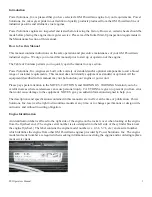
Power Solutions, Inc., industrial power units are equipped with instrument panels which contain shut down
gauges for High Engine Water Temperature and Low Engine Oil Pressure. A push button ‘Tattletale’ relay is
utilized with this system. When starting the engine it is necessary to ‘depress’ the safety switch override button,
until the engine starts and engine oil pressure is obtained (usually 2 to 5 seconds). The engine will continue to
run when the button is released.
CAUTION: If the engine does not continue to run when the button is released, it will be necessary to check the
instrument panel fuse and/or the engine lubrication system (i.e. oil level, etc.) before restarting the engine.
NOTE: Power Solutions, Inc. provides engines to many different original equipment manufacturers. Not all
manufacturers use the PSI instrument panel. Please refer to the equipment Operators Manual for instructions on
engine starting.
Fuel Systems
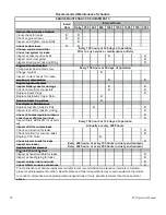
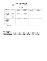
Several different fuel systems have been used on Power Solutions, Inc. GM Powertrain engines. A chart identi-
fying the different types of fuel systems used by engine model can be found in the back of this manual.
NOTE: Some fuel systems are installed by the original equipment manufacturer. Therefore it may be necessary
to contact the equipment manufacturer for information pertaining to your specifi c fuel system if it cannot be
found in the chart.
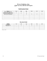
Governors
As with fuel systems, several different governor types have also been used with the Power Solutions, Inc. GM
Powertrain engines. A chart identifying the different types of governor systems used is included at the back of
this manual.
Summary of Contents for Titan 875
Page 43: ...4 10 Machine Maintenance...
Page 44: ...4 11 Machine Maintenance...
Page 45: ...4 12 Machine Maintenance...
Page 46: ...4 13 Machine Maintenance...
Page 47: ...4 14 Machine Maintenance...
Page 48: ...4 15 Machine Maintenance...
Page 49: ...4 16 Machine Maintenance...
Page 50: ...4 17 Machine Maintenance...
Page 51: ...4 18 Machine Maintenance...
Page 52: ...4 19 Machine Maintenance...
Page 53: ...4 20 Machine Maintenance...
Page 54: ...4 21 Machine Maintenance...
Page 55: ...4 22 Machine Maintenance...
Page 56: ...4 23 Machine Maintenance...
Page 57: ...4 24 Machine Maintenance...
Page 58: ...4 25 Machine Maintenance...
Page 59: ...4 26 Machine Maintenance...
Page 66: ...5 3 Water and Chemical System Figure 5 1 Flow Diagram D 6701 Rev A Sheet 1...
Page 67: ...5 4 Water and Chemical System Figure 5 2 Flow Diagram D 6701 Rev A Sheet 2...
Page 68: ...5 5 Water and Chemical System Figure 5 3 Flow Diagram D 6701 Rev A Sheet 3...
Page 71: ...6 3 Electrical System Figure 6 1 Electrical Schematic D 6700 Rev B...
Page 72: ...6 4 Electrical System Figure 6 2 Wiring Diagram D 6699 Rev B Sheet 2...
Page 73: ...6 5 Electrical System Figure 6 3 Wiring Diagram D 6699 Rev B Sheet 3...
Page 74: ...6 6 Electrical System Figure 6 4 Wiring Diagram D 6699 Rev B Sheet 4...
Page 86: ...8 3 Machine Assemblies and Parts List Figure 8 1 Machine Assembly Front Left View D 6600 Rev...
Page 87: ...8 4 Machine Assemblies and Parts List Figure 8 2 Machine Assembly Front Right View D 6600 Rev...
Page 88: ...8 5 Machine Assemblies and Parts List Figure 8 3 Machine Assembly Back Right View D 6600 Rev...
Page 89: ...8 6 Machine Assemblies and Parts List Figure 8 4 Machine Assembly Back Left View D 6600 Rev...
Page 91: ...8 8 Machine Assemblies and Parts List Figure 8 5 Frame Assembly Front Right View D 6601 Rev A...
Page 92: ...8 9 Machine Assemblies and Parts List Figure 8 6 Frame Assembly Front Left View D 6601 Rev A 1...
Page 93: ...8 10 Machine Assemblies and Parts List Figure 8 7 Frame Assembly Back Right View D 6601 Rev A...
Page 95: ...8 12 Machine Assemblies and Parts List Figure 8 8 Engine Assembly Front View D 6602 Rev F...
Page 96: ...8 13 Machine Assemblies and Parts List Figure 8 9 Engine Assembly Back Right View D 6602 Rev F...
Page 97: ...8 14 Machine Assemblies and Parts List Figure 8 10 Engine Assembly Back Left View D 6602 Rev F...
Page 101: ...8 18 Machine Assemblies and Parts List Figure 8 12 Solenoid Assembly C 6645 Rev A...
Page 103: ...8 20 Machine Assemblies and Parts List Figure 8 13 Idler Pulley Tensioner Assembly C 6660 Rev...
Page 105: ...8 22 Machine Assemblies and Parts List Figure 8 14 Blower Assembly Front View D 6603 Rev A...
Page 106: ...8 23 Machine Assemblies and Parts List Figure 8 15 Blower Assembly Back View D 6603 Rev A...
Page 108: ...8 25 Machine Assemblies and Parts List Figure 8 16 AirActuator Assembly C 6608 Rev...
Page 110: ...8 27 Machine Assemblies and Parts List Figure 8 17 Pump Silencer Assembly D 6604 Rev A...
Page 112: ...8 29 Machine Assemblies and Parts List Figure 8 18 Pump Assembly Back View D 6618 Rev C...
Page 113: ...8 30 Machine Assemblies and Parts List Figure 8 19 Pump Assembly Front View D 6618 Rev C...
Page 115: ...8 32 Machine Assemblies and Parts List Figure 8 20 Exhaust Assembly D 6607 Rev A...
Page 128: ...8 45 Machine Assemblies and Parts List Figure 8 27 Orifice Manifold Assembly C 6616 Rev A...
Page 134: ...8 51 Machine Assemblies and Parts List Figure 8 31 Poly Water Box 8G Assembly D 6619 Rev A...
Page 137: ...8 54 Machine Assemblies and Parts List Figure 8 33 Upper Dash Assembly C 6610 Rev A...
Page 139: ...8 56 Machine Assemblies and Parts List Figure 8 34 Inset Dash Assembly D 6611 Rev A...
Page 141: ...8 58 Machine Assemblies and Parts List Figure 8 35 GrillAssembly C 6727 Rev A...
Page 145: ...8 62 Machine Assemblies and Parts List Figure 8 37 Cover Catalytic Assembly D 6730 Rev...
Page 147: ...8 64 Machine Assemblies and Parts List Figure 8 38 Top Cover Machine Assembly D 6609 Rev B...
Page 156: ...8 73 Machine Assemblies and Parts List Figure 8 44 Dura Flow APOAssembly D 5654 Rev E...
Page 187: ...21...
Page 209: ...20 PSI Operators Manual 3 0L Engine Spark Plug Wire Routing...
Page 210: ...PSI Operators Manual 21 4 3L Engine Spark Plug Wire Routing...
Page 211: ...22 PSI Operators Manual 5 0L 5 7L Engine Spark Plug Wire Routing...