13
3. Priming the High-Pressure Pump:
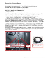
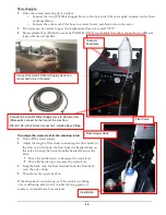
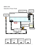
Once water is in the solution tank, the solution pump must be primed:
•
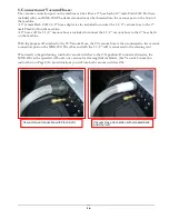
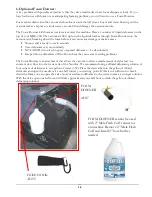
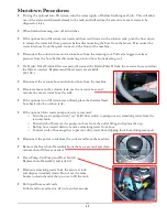
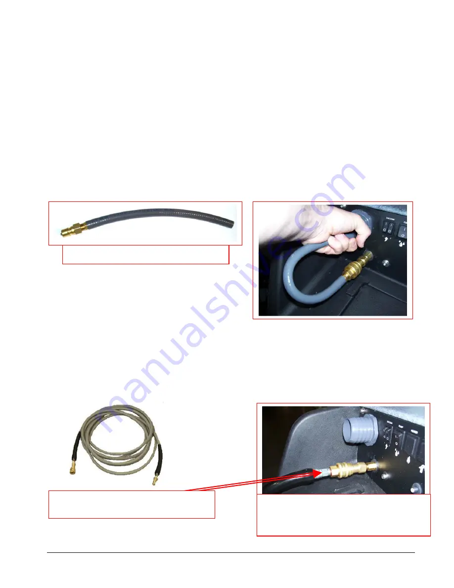
There is a priming hose included with the machine. Connect the priming hose to the solution outlet –
female quick connect on the front of the machine.
•
Turn on both vacuums and the solution pump. Insert the end of the priming hose into the vacuum
inlet port on the front of the machine and cup your hand around the hose to block off the vacuum
inlet with your hand. The vacuum will pull solution through the pump and priming hose into the
vacuum tank.
•
Turn off the pump and vacuums. Disconnect the priming hose. You can now continue your set-up.
As long as there is solution in the tank, the pump should remain primed.
If the pump still does not prime, or if flow is low or unsteady, check the hose from the solution tank to the
pump (as well as the filter) for clogging, kinks, or restrictions. Clean or replace hose and/or filter and repeat
the priming procedure.
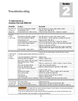
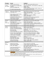
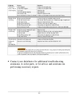
If you are having trouble with the pump, refer to the trouble shooting guide or contact your distributor for
advice or assistance.
4. Connection of Solution Hose:
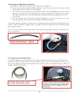
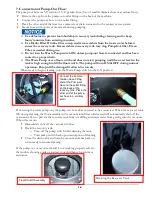
Connect the high pressure solution hose to the solution outlet (female quick connect on the front of the
machine). Connect the other end of the hose to the male quick connect on the cleaning tool. When you are
ready to start cleaning, turn the solution pump switch to the ON position. The pressure is preset, there is no
pressure adjustment to be made.
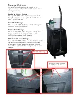
Connect the male end of the HP Solution Hose
Assembly to the female solution outlet fitting on
the machine. Connect the female end to the
cleaning tool.
HP Solution Hose Assembly – AH79D
1/4” id X 25’ with M-F Quick Connects
PUMP PRIMING HOSE – NM5080
Summary of Contents for Nautilus Extreme MXE-200
Page 1: ...1 LMANN20 Revised 02 16 2018 Nautilus MXE 200 Operating Manual EXTREME ...
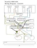
Page 23: ...23 M1200 Wiring Diagram Nautilus MXE 200 Wiring Diagram Cord 1 ...
Page 37: ...37 OPTIONAL AUTO FILL FLOAT VALVE ASSEMBLY NM5740 ...
Page 38: ...38 Pump Out Pump PARTS ASSEMBLY ...
Page 39: ...39 1 4 4 6 7 8 9 10 11 3 3 8 9 12 8 9 39 8 9 2 2 5 ...
Page 49: ...49 92 91 95 94 112 13 14 14A 104 105 1 39 PUMP OUT CONNECTIONS ...
Page 50: ...50 35 36 36A 78 36 36A 34 39 127 128 129 2 1 130 32 34 119 39 131 ...


