28
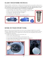
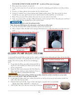
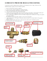
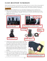
CLEAN CHEMICAL FEED FILTER & FOOT VALVE:
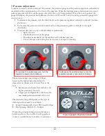
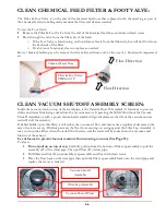
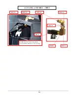
The Filter & Foot Valve is on the end of the chemical feed hose that is placed in the chemical jug as part of
the chemical feed system. Regularly examine the filter and clean as needed.
To test the Foot Valve:
•
Remove the Filter & Foot Valve from the end of the chemical feed hose and rinse in fresh water.
•
Blow through the valve from the filter side of the barb.
o
If the Foot Valve is functioning, air should move freely from the filter side, but will not flow from
the barb side of the filter.
o
If valve is not functional, clean or replace as needed.
Heavy chemical build-up can be removed with a mild acid rinse and/or the use of a brush and compressed
air.
CLEAN VACUUM SHUTOFF ASSEMBLY SCREEN:
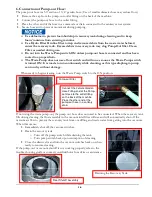
Inside the recovery tank, on top of the stand pipe, is the Vacuum Shutoff Assembly. It functions to prevent
debris and water from being sucked into the vacuum motors. Operating the MX1200 without the Vacuum
Shutoff Assembly or with a poorly maintained assembly will greatly decrease the life of the vacuum motors
and will void the warranty.
If debris builds up on this filter, it will reduce the vacuum air flow and may cause a significant decrease in the
rate of water recovery. If debris prevents the float from moving or seating against the Filter Cap Assembly, it
may not stop the airflow when the tank fill with water, and the water will be sucked into the vacuums and
blown out the exhaust.
Use defoamer to prevent foam or moisture from entering vacuums (See Page 15).
To clean:
•
Do not pull up on top of cap.
Carefully pull up from the bottom of filter cap assembly to pull the
assembly off of the stand pipe. Then pull float off of riser pipe.
•
Pull fibers and lint off and rinse filter cap assembly and float with clean water.
•
Place the float back on the riser pipe then push the filter cap assembly back onto the stand pipe and
replace the recovery tank lid.
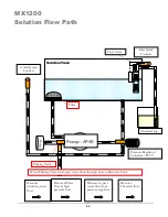
Flow Direction
Flow Direction
Vacuum Shutoff
Assembly
Filter & Foot Valve
PDE100-11P
Chemical Feed Hose
Vacuum Shutoff Float
Filter Cap Assembly
Summary of Contents for Nautilus MX1200
Page 1: ...1 LMANN01 Revised 01 29 2015 Nautilus MX1200 Operating Manual ...
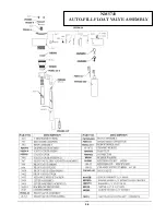
Page 39: ...39 NM5740 AUTO FILL FLOAT VALVE ASSEMBLY ...
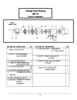
Page 41: ...41 Pump Out Pump AP37 PARTS ASSEMBLY ...
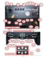
Page 42: ...42 1 2 3 5 4 4 6 7 8 9 10 8 12 3 8 9 11 9 23 100 104 2 9 8 39 ...
Page 49: ...49 2 39 1 72 73 73 67 9 30 31 82 83 2 83 82 84 INSIDE SOLUTION TANK BOTTOM VIEW SOLUTION TANK ...
Page 51: ...51 96 88 112 105 93 PUMP OUT PARTS 99 96 91 95 97 9 111 113 117 119 ...
Page 52: ...52 FLOW 81 92 91 99 96 9 97 105 13 14A 14 95 PUMP OUT PARTS 1 39 97 9 119 ...

