17
7. Pressure Adjustment:
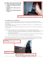
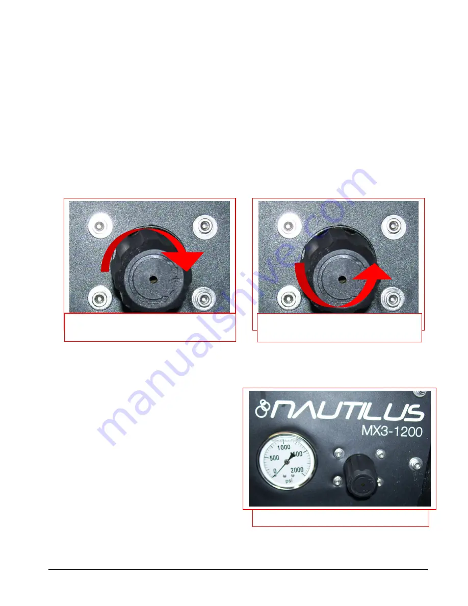
To make it easier to check and adjust the pressure, the pressure gauge and the pressure regulator/unloader are
mounted on the control panel on the front of the machine. When the high-pressure solution pump is on and
primed, pressure will show on the gauge only while the tool is being sprayed. When the tool is sprayed the
gauge will display the pressure being delivered to the tool. When the tool is not being sprayed the gauge will
return to zero.
•
To decrease the pressure, turn the black knob on the pressure regulator/unloader to the left (counter-
clockwise.)
•
To increase the pressure, turn the black knob on the pressure regulator/unloader to the right
(clockwise.)
•
To adjust pressure to your tool and surface requirements:
o
Spray the tool.
o
Check the pressure on the gauge.
o
Re-adjust as needed to set the machine at the desired pressure.
o
Choose the pressure setting that best meets your type of cleaning.
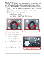
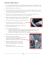
Pressure gauge & Regulator/Unloader
To increase the solution pressure, turn the
regulator/unloader knob clockwise.
To decrease the solution pressure, turn the
regulator/unloader knob counter-clockwise.
The maximum pressure setting is 1200psi;
however, the highest pressure attained is
dependent on the amount of water flow at the
tool:
•
Smaller jets and lower flow will allow for
higher pressure at the tool.
•
Larger jets and higher flow will lower the
maximum pressure attained at the tool.
The desired setting will depend on the type of
cleaning and tool used. For example:
•
Carpet Cleaning with 2-jet AW29 wand: 400psi
•
Tile Cleaning with SX-15: 1000psi
If adjusting or maintaining pressure becomes a
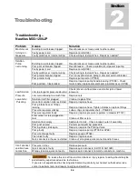
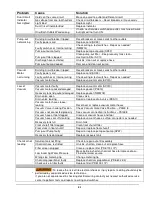
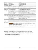
problem, refer to the trouble shooting guide or
contact your distributor for advice or assistance.
Summary of Contents for Nautilus MX3-1200JP
Page 1: ...1 LMANN19 Revised 01 29 2015 Nautilus MX3 1200JP Operating Manual ...
Page 39: ...39 NM5740 AUTO FILL FLOAT VALVE ASSEMBLY ...
Page 41: ...41 Pump Out Pump AP37 PARTS ASSEMBLY ...
Page 42: ...42 1 2 3 5 4 4 6 7 8 9 10 8 9 3 8 9 8 9 23 100 104 12 11 2 39 ...
Page 49: ...49 2 39 1 72 73 73 67 9 30 31 82 83 2 83 82 84 INSIDE SOLUTION TANK BOTTOM VIEW SOLUTION TANK ...
Page 51: ...51 PUMP OUT CONNECTIONS 96 88 112 105 93 99 96 91 95 97 9 111 113 117 119 ...
Page 52: ...52 FLOW 81 92 91 99 96 9 97 105 13 14A 14 95 PUMP OUT PARTS 1 39 9 97 119 ...

