background image

  25 


VAC 1 

PUMP OUT 

SOL PUMP 


Machine Base 


Dual Circuit 
Indicator 

VAC 2 

PUMP OUT 


CORD #2 


SOLUTION 
PUMP 

12GA 

12/3  

GREEN 

CIRCUIT BREAKER 
20AMP 

MX3-1200 
Wiring Diagram – Cord #2 

Summary of Contents for Nautilus MX3-1200JP

Page 1: ...1 LMANN19 Revised 01 29 2015 Nautilus MX3 1200JP Operating Manual ...

Page 2: ... Electrical Supply 9 Water Supply Chemicals 10 Solution Hose Pump Priming 13 Vacuum Hoses 14 Foam Downer 15 Pump Out System 16 Pressure Adjustments 17 Shutdown Procedures 18 Accessory Storage 19 Troubleshooting 20 Solution Flow Path 23 Wiring Diagrams 24 SECTION 3 Maintenance Technical Maintenance 27 Drawings Parts Lists o Pump 36 o Auto Fill 38 o Pressure Unloader 40 o Pump Out Pump 41 o Parts Pi...

Page 3: ...o properly operate and maintain the machine and to ensure that the equipment operates at its maximum performance level All users must read and understand this manual completely before operating the machine Always maintain this manual in legible condition adjacent to the Nautilus MX3 1200JP or place in a secure location for future reference Any questions pertaining to the operating or servicing of ...

Page 4: ...d Equipment MX3 1200JP High Pressure Extractor Vacuum Connection 2 Barb or 2 Male Flash Cuff with 2 Male NPT Vacuum Hose 25 X 1 1 2 with 1 1 2 cuff 2 cuff 4 x 1 1 2 with 2 cuffs 2 Female Flash Cuff x 1 1 2 hose adapter Hydro Filter II Inline Filter AC10 HP Solution Hose 25 x 1 4 with 1 4 male female quick connects Accessory Mount Hardware Four 1 4 20 x 5 8 SS Screws Washers Auto Fill System with c...

Page 5: ... Hand Tool AR53 1 1 2 Vacuum Hose Sold per foot No cuffs AH36 2 cuff for 1 1 2 Vac Hose AH46 1 1 2 cuff for 1 1 2 Vac Hose AH42 1 1 2 Hose Connector PVC AH74 HP Solution Hose 1 4 X 25 w M F Quick Connects AH79D 1 4 Male Quick Connect AH102B 1 4 Female Quick Connect AH101B Pump out Hose AH65 Hydro Filter II AC10 Replacement Screen for Hydro Filter II AC10C Metering Tip Kit PDE001 12 3 X 50 Power Co...

Page 6: ...as the plug No plug adapter should be used with this machine The power cords supplied with this machine are properly sized to handle the electrical load of this machine and properly grounded as described above Any extension cords used with this machine must be similarly sized with an equal or greater load rating and grounded to assure safe operation A properly sized or rated GFCI protected cord ca...

Page 7: ...res above 140ºF Rinse the solution tank chemical system and pump with fresh water after each day s use Do not allow pump to run dry Always maintain adequate solution level to supply solution pump HP hoses may rupture if worn or damaged Do not use HP solution hoses if hose covering is cut bulging or otherwise damaged Examine HP solution hoses daily and replace or repair hoses as needed Use Hydro Fi...

Page 8: ... parallel 1 Connect the discharge exhaust hose from vacuum 1 to the exhaust pipe on machine base 2 Place the rubber stopper into the vacuum inlet port of vacuum manifold number two 3 Open vacuum gate valve and attach the Gatekeeper to prevent accidental valve closure When connected in parallel both vacuums must be running during cleaning Vacuums cannot be operated individually To connect vacuums i...

Page 9: ...or continuous operation 20amp circuits are usually found in kitchens and bathrooms Make sure no other items are plugged into these circuits An overloaded circuit will not always trip the circuit breaker immediately but it may not provide sufficient voltage for proper operation and the breaker may trip eventually Plug the two power cords into two outlets from different circuits If the Dual Circuit ...

Page 10: ...he metering tip and the dilution rate can only be changed by changing the metering tip See How to Change the Metering Tip on Page 11 for instructions Chemical Feed Setup Remove the chemical feed hose from the solution tank Make sure float is attached to valve and hanging freely above the bottom of the solution tank Adjust float height to maintain adequate water level Place the end of the chemical ...

Page 11: ... rates are based on chemicals with water like viscosity Thicker more viscous chemicals will dilute at a different rate For powdered chemicals a liquid concentrate must be made Mix the concentrate according to the manufacturer s directions and then select the appropriate metering tip Contact your distributor or Hydro Force if you have questions about your chemical Metering Tip Application Chart Met...

Page 12: ... to the float valve Unhook the float from the beaded chain on the valve Unsnap the hook from the beaded chain on the float Move the bottle down to decrease the water level Move the bottle up to increase the water level Snap the back onto the float chain hook the float back onto the valve chain Turn the water supply back on If the chemical is not drawing or if the tank is not filling or is overflow...

Page 13: ...The vacuum will pull solution through the pump and prime valve into the vacuum tank Let off the prime valve and your pump is primed As long as there is solution in the tank the pump should remain primed You can now proceed with cleaning or turn the pump off and continue your set up If the pump still does not prime or if flow is low or unsteady check the hose from the solution tank to the pump as w...

Page 14: ...e machine using the appropriate cuff and the other to the outlet side of the Hydro Filter 2 A Hydro Filter II inline filter 3 A 25 Vacuum Hose The 2 cuff on the 25 vacuum hose is connected to the inlet side of the hydro filter The other end with the 1 1 2 cuff is connected to the cleaning tool When ready to begin cleaning turn both vacuum switches to the ON position If connected in series the MX3 ...

Page 15: ...ry economically NO LABOR is involved to spray or spread defoamer it s all automatic Keeps silicone defoamers off the floor where they can cause resoiling problems The Foam Downer is an attachment that allows the vacuum to draw a small amount of defoamer in a constant slow flow into the waste tank of the Nautilus We recommend using a diluted defoaming solution of four ounces of defoamer to one gall...

Page 16: ...n continuously while cleaning as this type diaphragm pump can run dry without damage When ready to begin cleaning turn the Waste Pump switch to the ON position If not using the waste pump out the pump out hose does not need to be connected When the recovery tank fills during cleaning the float assembly in the vacuum inlet filter will rise and will automatically shut off the vacuum air flow to prev...

Page 17: ...tool o Check the pressure on the gauge o Re adjust as needed to set the machine at the desired pressure o Choose the pressure setting that best meets your type of cleaning Pressure gauge Regulator Unloader To increase the solution pressure turn the regulator unloader knob clockwise To decrease the solution pressure turn the regulator unloader knob counter clockwise The maximum pressure setting is ...

Page 18: ...m hose and solution hose from the machine If water remains in the solution tank use the short vacuum hose and vacuum the excess water from the tank If the auto fill system was utilized place the chemical feed hose back into the solution tank If the waste pump out system was used o Turn the waste pump switch on to pump out any remaining water from the recovery tank o Turn switch off remove the pump...

Page 19: ...he MX3 1200JP has two sets of cord wraps to hold two 12 3 x 50 power cords Carpet Wand Storage The front of the MX3 1200JP is designed to hold a S Bend Carpet wand and has two straps to hold it securely Optional strap for larger wands available Other Storage Each side of the MX3 1200JP has a set of molded in threaded inserts to which holders can be attached to hold other accessories or supplies ma...

Page 20: ... from solution tank restricted Repair or replace hose Pump intake hose or fittings leaking Repair or replace hose Tighten clamps or replace fittings Pressure regulator sticking Lube o rings on regulator shaft PAGE 33 Pressure regulator faulty Repair or replace pressure regulator unloader PT017 Filter screen or jets plugged on tool Clean out filter or jets Solution tank empty Add water to tank Chec...

Page 21: ...aged Replace gasket NM5718 Drain valve open Close valve Drain valve leaking Repair or replace drain valve PEA11 Vacuum motor hoses loose leaking Reconnect or replace vacuum motor hoses Vacuum Valve in wrong Position Check Vacuum Gate Valve Position PAGE 8 Vacuums not connected properly See vacuum connection instructions PAGE 8 Vacuum hose or tool clogged Clean out vacuum hoses and tool Vacuum hose...

Page 22: ... connects AH101B AH102B Solution tank Float too heavy Filled with water Replace float overflowing Float chain tangled Make sure float chain free hanging properly Float too high Adjust chain to set float at proper level Water Pressure too high Use pressure regulator on auto fill hose Float valve faulty Repair or replace float valve Chemical Jug Foot valve in Filter stuck Clean out foot valve and fi...

Page 23: ...hemical Jug Denotes Water flow in high pressure hose Denotes Chemical flow Denotes by pass water flow from pressure regulator Denotes incoming water flow MX3 1200 Solution Flow Path Float Valve Inlet Quick Connect Priming Valve When Priming Valve held open water flows through hose to Recovery Tank ...

Page 24: ...24 M1200 Wiring Diagram MX3 1200 Wiring Diagram Cord 1 VAC 1 PUMP OUT SOL PUMP Machine Base COOLING FAN Dual Circuit Indicator VAC1 VAC2 VAC 2 CORD 1 12GA 12 3 CIRCUIT BREAKER 20AMP SOLUTION PUMP ...

Page 25: ...25 VAC 1 PUMP OUT SOL PUMP Machine Base Dual Circuit Indicator VAC 2 PUMP OUT CORD 2 SOLUTION PUMP 12GA 12 3 GREEN CIRCUIT BREAKER 20AMP MX3 1200 Wiring Diagram Cord 2 ...

Page 26: ... Do not turn Waste Pump Switch ON unless a hose is connected to the Pump out Outlet port For pump protection there is a pressure switch which will turn the waste pump off if the pressure in the discharge line gets too high as it would if the pump was turned on while the outlet cap was still in place Vacuum 1 Power from Cord 1 When the switch is turned to the ON position power is supplied to the va...

Page 27: ...ds Failure to do so may result in severe personal injury or death OPERATION INTERVAL Page CLEAN CHEMICAL FEED FILTER FOOT VALVE Daily After Each Job 28 CLEAN VACUUM SHUTOFF ASSEMBLY SCREEN Daily After Each Job 28 CLEAN HYDRO FILTER II Daily After Each Job 29 RINSE OUT RECOVERY TANK Daily 29 CLEAN WASTE PUMP OUT PUMP Daily 30 FLUSH SOLUTION TANK AND PUMP Daily 30 CLEAN PUMP INLET FILTER Weekly As n...

Page 28: ...0JP without the Vacuum Shutoff Assembly or with a poorly maintained assembly will greatly decrease the life of the vacuum motors and will void the warranty If debris builds up on this filter it will reduce the vacuum air flow and may cause a significant decrease in the rate of water recovery If debris prevents the float from moving or seating against the Filter Cap Assembly it may not stop the air...

Page 29: ...he o ring lid seal and replace as needed Re install the new or cleaned screen Screw the lid back onto the body and turn clockwise to tighten RINSE OUT RECOVERY TANK Build up of fine silt sand and other debris in the recovery tank can damage the Drain Valve and Waste Pump if so equipped Hair and fibers in the recovery tank can clog the vacuum filter and Pump out filter if so equipped Clean out the ...

Page 30: ...the solution tank With Cords 1 2 plugged in connect a solution hose to the solution outlet female quick connect The other end of the hose should have an open quick connect or no quick connect to allow full flow out of the hose Direct the open end of the solution hose into the recovery tank vacuum barb Turn one or both of the vacuums ON and turn the solution pump ON Let the pump run until most of t...

Page 31: ...f the recovery tank Close the drain valve and dispose of the water CLEAN PUMP INLET FILTER A restricted Pump Inlet Filter can prevent the solution pump from providing adequate pressure for cleaning A restriction or air leak on the pump inlet hose can also damage the solution pump check valves and plunger seals To examine the filter open the solution tank lid on the front of the machine The filter ...

Page 32: ...e proportioner and mixed with the incoming water The metering tip can be removed from the proportioner to speed up the process Once the rinse solution has been drawn through the proportioner turn off the water faucet and disconnect the Auto Fill Water Supply Hose Plug in Cord 1 connect the short 4 vacuum hose to the vacuum barb turn on one or both vacuums and use the short vacuum hose to remove th...

Page 33: ... piston screw so they can be removed from the stem retainer 6 Use a synthetic grease with Teflon such as Ultra Slick or Super Lube to lubricate the o rings on the piston and spindle assembly 7 Re install the piston and spindle assembly into the retainer and tighten 8 Apply thread sealant to the threads of the stem retainer and screw the retainer back into the regulator body and tighten 9 Replace s...

Page 34: ...for deep scratches Deep scratches will allow water to flow past gaskets and leak from valve Replace valve if needed Examine the gaskets and replace if cut torn or deformed Raised rounded side of gasket goes toward valve slide Larger flat sides seat on ring on flange and outlet adapter Sand and debris will collect in the bottom of the valve body and prevent the slide from going down and seating pro...

Page 35: ... pump switch to the ON position and perform the pump priming procedure Hold the priming valve open for a few extra seconds to be sure the anti freeze has passed through the priming valve When the pump is primed allow the anti freeze to circulate for 5 10 minutes Mix and add more anti freeze solution as needed Make sure end of chemical feed hose stays submerged in the anti freeze solution This will...

Page 36: ...36 Parts Replacementpartsavailableforrepairof yourMX3 1200JP Section 3 KIT A PT042 KIT B PT044 KIT C PT045 MX3 1200JP PUMP AP48 PARTS ASSEMBLY ...

Page 37: ...lve Assembly 4 0205 0014 9 O RING FOR VALVE 4 C0100 1116 10 PLASTIC SPACER RING 8 0205 0016 11 GUIDE VACUUM SEAL RETAINER 2 0311 0012 12 VACUUM SEAL 2 0311 0010 13 O RING FOR VACUUM SEAL 2 C0100 1117 14 BEARING ASSEMBLY 1 0300 1000 0001 ECCENTRIC INSERT Part of 14 Bearing Assembly 1 0300 0001 0XXX BEARING 6205 Part of 14 Bearing Assembly 1 C3000 0003 15 SOCKET HEAD CAP SCREW 2 C100 0504 16 WASHER ...

Page 38: ...38 AUTO FILL ASSEMBLY M013 NM5740 Float Valve Assembly See Parts Breakdown on Next Page BR286 BR286 BR138 NM5751 NM5751 BR282A AH102B BR282A ...

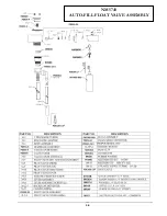
Page 39: ...39 NM5740 AUTO FILL FLOAT VALVE ASSEMBLY ...

Page 40: ...AT 2 BRASS KNOB 10 PISTON RETAINER O RING 18 BRASS BODY 3 LOCKING NUT 11 PISTON O RING SMALL 19 POPPET O RING 4 SPRING 12 PISTON WASHER SMALL 20 POPPET 5 SPRING PLATE 13 SPINDLE O RING 21 POPPET SPRING 6 PISTON 14 SPINDLE SPACER 22 OUTLET RETAINER O RING 7 PISTON WASHER LARGE 15 SPINDLE 23 OUTLET RETAINER REPAIR KIT PT017KIT INCLUDES PARTS 6 15 PT017 HP UNLOADER ...

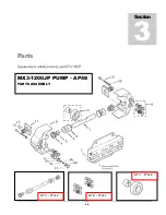
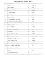
Page 41: ...41 Pump Out Pump AP37 PARTS ASSEMBLY ...

Page 42: ...42 1 2 3 5 4 4 6 7 8 9 10 8 9 3 8 9 8 9 23 100 104 12 11 2 39 ...

Page 43: ...43 8 9 15 16 17 18 8 9 21 22 23 24 32 32 37 38 39 40 40 40 41 41A 55 56 9 CONTROL PANEL REAR VIEW BASE BASE SKIRT HINGE SCREWS 19 19A 25 104 100 55 56 20 23A ...

Page 44: ...44 27 27A 28 29 29 31 31 9 9 32 32 33 34 35 38 37 1 39 13 14 14a 30 30 26 REAR VIEW BASE BASE SKIRT RECOVERY TANK VACUUM PLUG ASSEMBLY 109 106 107 108 36 79 103 114 ...

Page 45: ...45 32 32 43 44 45 37 46 46 47 48 50 9 50 9 51 53 3 58 59 TOP VIEW OF BASE 3 58 59 52 39 55 56 55 56 106 47A 47 60 60 115 115 118 ...

Page 46: ...46 48 49 49 47 47 47A 47 47A 47 47A 47A 51 51 37 9 54 64 9 54 64 9 54 64 52 VACUUM MOUNTS CONNECTIONS ...

Page 47: ...47 66 69 68 70 71 PUMP PRIMING VALVE BOTTOM VIEW OF BASE 45 71 110 67 68 65 60 60 3 59 37 39 61 62 57 56 9 54 9 54 63 55 3 59 61 62 122 44 117 ...

Page 48: ...48 9 41 2 BOTTOM VIEW SOLUTION TANK BASE SKIRT 72 1 73 9 9 8 8 39 74 75 76 77 77 78 34 36 36A 30 30 2 120 121 31 80 55 ...

Page 49: ...49 2 39 1 72 73 73 67 9 30 31 82 83 2 83 82 84 INSIDE SOLUTION TANK BOTTOM VIEW SOLUTION TANK ...

Page 50: ...50 101 102 VACUUM SHUTOFF ASSEMBLY 91 86 92 86 88 89 90 85 81 INSIDE RECOVERY TANK WITH PUMP OUT FILTER IN PLACE INSIDE RECOVERY TANK VACUUM SHUTOFF AND PUMP OUT FILTER REMOVED 116 87 85 ...

Page 51: ...51 PUMP OUT CONNECTIONS 96 88 112 105 93 99 96 91 95 97 9 111 113 117 119 ...

Page 52: ...52 FLOW 81 92 91 99 96 9 97 105 13 14A 14 95 PUMP OUT PARTS 1 39 9 97 119 ...

Page 53: ...840 WAND HOLDER STRAP LONG TOP STRAP 30 NM5014 WASHER LOCK SS 11 NM5844 WAND HOLDER BUCKLE 31 NM4063 SCREW 20 X SOCHD SS 12 NM5842 WAND HOLDER STRAP SHORT BOTTOM STRAP 32 NM5722 WHEEL 12 with HUB CAP 13 BR319 ADAPTER MPT X MGH NS NM5010 AXLE CAP PUSH NUT 14 BR325 GARDEN HOSE CAP 33 NM4447 GREEN NEON LIGHT 120V 14A BR600 GARDEN HOSE WASHER 34 NM5754 COOLING FAN 15 AH68 BARB 2 X 2 MPT PVC 35 NM5757 ...

Page 54: ...2 SCREW 6 X PPH SS QTY 6 52 PA051 HOSE CLAMP 2 2 75 78 NM5756 FAN GUARD WIRE FORMED 53 NM5705 DECAL VAC CONNECTION 79 NM4031 NUT 6 32 NYLOCK SS 54 NM5133 SCREW 20 X 2 SOCHD SS 80 NM5124 SCREW 8 32 X PPH SS 55 NM5793 NUT 8 32 NYLOCK SS 81 NM5746 FILTER SS FPT 56 NM5124 SCREW 8 32 X PPH SS QTY 6 82 NM5098 BULKHEAD FITTING 3 8 57 NM5752C LATCH SLIDE QTY 2 83 BR284 ELBOW 90DEG 3 8 STREET 58 NM5120 SCR...

Page 55: ...WASHER 5 16 FLAT FENDER 103 NM5705B DECAL DUAL CIRCUIT LIGHT NS NM5703 WIRING HARNESS UPPER 104 BR282A ELBOW 90DEG LONG STREET NS NM5701 WIRING HARNESS LOWER 105 BR049 BARB X FPT NS NM5758 KIT DUAL CIRCUIT WIRING 106 PHY106 028 RUBBER VACUUM PLUG NS NM5711 DECAL NAUTILUS SIDE QTY 2 107 NM4263 SCREW TEK 10 X 5 8 SS NS NM4087 SCREW 1 4 20 X 63 SOC BH SS 108 NM4460 CABLE NS NM5434 6 INTERNAL STAR WAS...

Page 56: ...SOLD PER INCH 32 BOTH ENDS HOSE CLAMP PH07 SOLUTION HOSE PRIME VALVE TO REC TANK 3 8 ID CLEAR COIL NM5082 SOLD PER INCH 27 BOTH ENDS HOSE CLAMP NA2250 HP HOSE 1 PUMP TO UNLOADER HP PULSE SOLD ASSEMBLED 50 ITEM 30805 BOTH ENDS 3 8 MS HP HOSE 2 PUMP TO GAUGE HP PULSE SOLD ASSEMBLED 45 ITEM PH509 GAUGE END MS PUMP END 3 8 MS HP HOSE 3 UNLOADER TO HP HOSE 4 HP PULSE SOLD ASSEMBLED 17 ITEM PH505 UNLOAD...

Page 57: ...hall not apply to defects resulting from improper operation lack of maintenance unauthorized modification chemical incompatibility misuse abuse or exposure to freezing temperature conditions It does not cover normal wear items such as o rings valve seals pump seals hoses jets cords batteries or other items which require replacement as a result of ordinary usage To obtain warranty service for the N...

Reviews: