15
7. Optional Foam Downer:
A key problem with portable extractors is that they have small tanks where foam dissipates slowly. If you
have had issues with foam or are anticipating foaming problems, you will want to use a Foam Downer.
Foam can be drawn into the vacuums before the vacuum shutoff closes. Foam and water blowing out the
vacuum makes a big mess, can decrease vacuum lift and damage the vacuum motors.
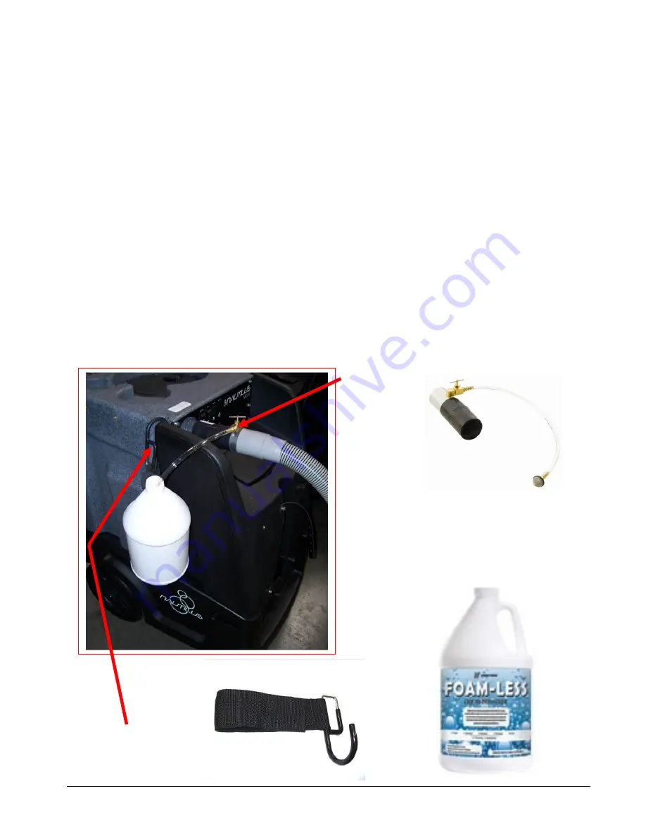
The Foam Downer kills foam as waste water enters the machine. Place a container of liquid defoamer on the
top of your MX3-500HE. The vacuum air flow siphons the liquid defoamer through Foam Downer into the
vacuum tank, breaking down the foam before it can cause any damage or make a mess.
•
Mounts and is ready to use in seconds
•
Uses defoamer very economically
•
NO LABOR is involved to spray or spread defoamer – it’s all automatic
•
Keeps silicone defoamers off the floor where they can cause resoiling problems
The Foam Downer is an attachment that allows the vacuum to draw a small amount of defoamer in a
constant slow flow into the waste tank of the Nautilus. We recommend using a diluted defoaming solution of
four ounces of defoamer to one gallon of water (1-32) or 31.25ml per liter. Place the draw tube into the gallon
of diluted defoamer and open the needle valve one half turn as your starting point. If this is not sufficient to
break down the foam you can open the valve more or add more defoamer to the water to make a stronger
solution.
With the valve open one half turn it will take approximately one half hour to drain the gallon of diluted
defoaming solution.
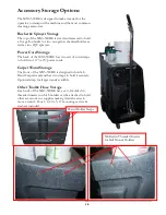
FOAM
DOWNER
AH17
FOAM DOWNER cannot be used
with 2” Male Flash Cuff connector
on machine. Remove 2” Male Flash
Cuff and install 2” hose barb as
needed.
HOSE HOOK
AH95
Summary of Contents for Nautilus MX3-500HE
Page 1: ...1 LMANN18 REVISED 01 29 2015 MX3 500HE Nautilus Operating Manual ...
Page 39: ...39 OPTIONAL AUTO FILL FLOAT VALVE ASSEMBLY NM5740 ...
Page 40: ...40 Optional Pump Out Pump AP37F PARTS ASSEMBLY ...
Page 41: ...41 2 4 4 6 7 10 11 3 8 9 3 5 1 8 9 8 9 2 39 12 8 9 ...
Page 48: ...48 2 39 1 72 73 73 67 9 30 31 82 83 2 83 82 84 INSIDE SOLUTION TANK BOTTOM VIEW SOLUTION TANK ...
Page 50: ...50 96 91 97 9 88 111 94 105 93 OPTIONAL PUMP OUT CONNECTIONS 99 95 118 ...
Page 51: ...51 FLOW 81 92 91 99 96 9 97 105 13 14A 14 95 OPTIONAL PUMP OUT PARTS 1 39 97 9 118 ...
Page 52: ...52 HEATER PARTS 42 42A 98 114 110 71 113 114 ...


