background image

Summary of Contents for 310-0500/0750

Page 1: ...AIRS GENERAL INFORMATION DISASSEMBLY PROCEDURES DISASSEMBLY PROCEDURES DISASSEMBLY PROCEDURES DISASSEMBLY PROCEDURES DISASSEMBLY PROCEDURES RECONDITIONING AND REPLACEMENT OF PARTS ASSEMBLY PROCEDURES ASSEMBLY PROCEDURES ASSEMBLY PROCEDURES ASSEMBLY PROCEDURES ASSEMBLY PROCEDURES ASSEMBLY PROCEDURES OIL FILL START UP PROCEDURES 310 0500 PARTS DRAWING PARTS LIST 310 500 0750 IHT PARTS DRAWING PARTS ...

Page 2: ......

Page 3: ... General Information 7 Shaft Seal 7 Parking Brake 8 Control Arm Friction Pack 8 Oil Level 8 MajorRepairs 9 19 GeneralInformation 9 DisassemblyProcedures 9 13 Reconditioning Replacement of Components 13 AssemblyProcedures I4 19 Oil Fill Start up Procedures 19 310 0500 Parts Drawing Parts List 20 21 310 0750Parts Drawing Parts List 22 23 Product Line 24 Page2 310 0500 07501HT ...

Page 4: ...displace ment motor uses a f i x e d swashplate Thepumpand motor are of the axial piston design and both utilize spherical nosed pistons which are held against a thrust race by internal compression springs The IHT has a self contained fluid supply and an integral filter The fluidisforced through the filter by a positive head on the fluid inthe housing reservoir with an assist by the negative press...

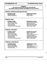
Page 5: ...may result inthe lossof hydrostatic braking capacity Proper brake main tenance becomes very important shouldthis condition develop Maintenance Check the transaxle cooling fan for broken or distorted blades and check to see that the fanis securely fas tened Replace the fan if damaged NOTE Notallvehicles are equipped with a cooling fan referto your vehicle manual Keep the transaxle clean Grass clipp...

Page 6: ...LEVEL PROPER SETTING CONDITION FOR EXCESSIVE DRIVE BELT VEHICLE LOAD DEBRIS BUILDUP DEFECTIVE DEFECTIVE CHANGEOIL DEBRIS REPLACE VEHICLE LOAD REPLACE TRANSAXLE NOISY UNDER LOAD LEVEL IN VALVE LINKAGE VEHICLE LOAD HIGH DEFECTIVE DEFECTIVE I I I ADJUST BYPASS VALVE LINKAGE I f FILL TO VEHICLE LOAD TO PROPER TRANSAXLE REPAIR OR LINKAGES AND METAL TO METAL CONTACT POINTS DEFECTIVE I I REWIRE TRANSAXLE...

Page 7: ...replace loose parts Repair or replace linkage SYMPTOM LOW POWER POSSIBLE CAUSE Check engineRPM Check drive belt pulleys Checkoil level condition Check for excessive loading Check brake setting Check for loose parts Check bypass valve linkage operation CORRECTIVE ACTION Adjust to correct setting Repair or replace Fill to proper level or change oil Reduce vehicle loading Adjust braketo proper settin...

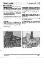
Page 8: ...axle These seals can be replaced without major disassembly o f the unit Replacement of these seals generally requires removal of the transaxle from the machine frame To remove the input shaft seal carefully pull the seal out of the housing bore with a hook type tool or a slide hammertype puller Care must betakentoavoid damage to the housing bore or to the shaft sealing surface Lubricate the new se...

Page 9: ...Variatlons Control Arm Friction Pack NOTE The control arm and friction pack vary between modelsand is notusedonsome The OEM have established individual specifications for the proper ad justments Refer to vehicle service manual for the proper procedures OLD NON ADJUSTABLEFRICTION NEW ADJUSTABLEFRICTION I Friction Pack Variations Oil Level To check the oillevel you must first remove the breather fit...

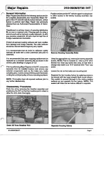
Page 10: ... IHT remove the transaxlefrom its installedlocation and removeany externalcomponentssuchasthebrakearm brake actuating pins control arm and friction pack if included cooling fan and input pulley or frame mounting hardware NOTE Thoroughly cleanall exposed surfaces prior to any further disassembly Disassembly Procedures Drain the oil by removing the breather assembly and positioning the IHT sothat th...

Page 11: ...erential bevel gears by rotating the axle ends I n s p e c t the final drive gear teeth for excessive wear or damage Check the differential assembly screws for proper For the 310 0500they should be torqued to 16 1 8ft lbs while the 310 0750 should betorquedto 12 14ft lbs I n s p e c tthe journal bearings inside the differential hous ingforexcessivewearbyfeelingtheshaftsforan unreasonable amount of...

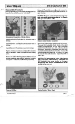
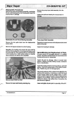
Page 12: ...retaining the center section in the upper housing CAUTION Thepump and motorpiston springs may push the center section assembly out of position while you remove thesebolts Remove CenterSection Assembly Remove the center section assembly from the housing The pump block assembly should remainin the upper housing on the input shaft but may stick to the center section Check the check valve plate boltto...

Page 13: ...tons should fitwith very little side clearancein the blockbores but must slide freely NOTE Thecorrectborediameterfortheblockis0 6295 to 0 6303and the pistons should be 0 6288 to 0 6291 Remove Pump Block Assembly For 310 0750 ModelsOnly Removethe two internal hexheadcapscrewsretainingthejackshaft to the housing with a 5mm hex wrench and remove the jack shaft pinion gear assembly from the housing Re...

Page 14: ...on housing and remove thedisplacement control shaft and lip seal Inspect the housing for damage Reconditioning and Replacement of Parts All partsshould be thoroughlycleanedinasuitable solvent Allsealant material MUST beremoved from the housing halves prior to reassembly I n s p e c t all partsfordamage nicksorunusualwear patterns Replace all parts having unusual excessive wear or discoloration Ins...

Page 15: ...age or for on the displacement control shaft Use a tool such as a eign material screwdriver to hold the guide block in position while Install the displacement control shaft shaft installing the swashplate Install Displacement Control Shaft Swashplate Installation Install the pump input shaft assembly and retaining ring Install the thrust washer and and pump block spring ont into the housing the pu...

Page 16: ...s Actuator Install the washers and a new lip seal onto the motor shaft Install Pump Block Kit Install the motor shaft into the center section For 310 0750Models 0nly lnstall the pinion gear and washers onto the jackshaft Install the jackshaft assem bly into the housing and toquetheb o l t sfrom120in lbs to 170 in lbs Install Motor Shaft Install the bypass plate small end first into the center sect...

Page 17: ...nd pump input shaft until seated on mounting bosses While holding the center section in position toque the bolts evenly from525 in lbs to 700 in lbs Install Center Section Assembly Install the motor thrust bearing with the thicker race towards the pistons by compressing the piston springs and sliding the bearing assembly in to place NOTE The tool being shown isan example of what you will need to c...

Page 18: ...g and apply the sealant as shown inthe followingtwo examples NOTE The drawings below may not appear the same as thefactorysealantapplication butaretherecom mended patterns Apply sparingly NOTE Sealantmustbeofgoodquality oil andheat resistant Install Differential Axle Assembly 3109500 Sealant Application Install a new filter onto the center section check valve plate Install the rotors and stators I...

Page 19: ...osition the transaxle assembly and check the bypass actuator and axle shafts for freedom of movement The axle shafts should not lock up but may be tight while the bypass actuator must rotate freely Torque the nut on the brake bolt from 120to 185 in Ibs Tighten Brake BoltNut Install a new lip seal on the displacement control shaft bypassactuatorasdescribedinthe Minor Repairs Sec tion Installthe bra...

Page 20: ...ct volume for fill should be 2 quarts 80ounces forboththe310 0500 and the 310 0750 Itis recommendedthattheunit be purgedpriorto installing into the vehicle frame The following is the suggested purging procedures for repaired transaxles 1 Spintheinput shaft inaclockwisedirectionat 1000 1500 RPM This maybeperformed in a drill press or equivalent 2 Engage actuate the bypass 3 Strokethecontrolleverfor...

Page 21: ...Page20 310 0500 0750IHT ...

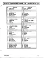
Page 22: ...RETAINING 49 LOWER HOUSING 63 SPACER 24 CUP WASHER 72 SEAL LIP 25 BRAKE STOP 108 BRAKE ROTOWSTRATOR ASSEMBLY 41 SPEED ADJUSTMENT SCREW 107 HEX LOCK NUT 5 16 24 40 FLANGE HEX SCREW 5 16 24 x1 105 BOLT 5 16 24 x 1 3 4 39 SPACER 103 ACTUATING PIN 38 NUT 10 24 102 BRAKE ARM 37 SOCKET HEAD CAP SCREW 101 RETAINING RING 36 CONTROL ARM 100 BYPASS ARM 35 OIL FILTER ELEMENT 34 SLEEVE BEARING 98 WASHER 29 BL...

Page 23: ...62 Page22 310500107501HT ...

Page 24: ...R 41 BRAKEROTOR STATOR ASSEMBLY 131 VENT BUSHING 43 WASHER 7 16 x 7 8 x 060 132 METAL VENT 44 DIFFERENTIAL ASSEMBLY 134 SLOTTED NUT 52 WASHER 3 4 x 1 5 x 13 135 COTTERPIN 53 SEAL 75 X 1 25X 250 139 COMPRESSION SPRING 310 0500 750IHT Page23 ...

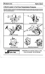
Page 25: ...h awide range of hydrostatic transaxles transmissions and pumps Hydro Gear and itsassociate companies provide complete worldwide service parts repair and technical assistance Bantam Duty Pumps 210 1010s Transaxles 210 3010LHeavy DutyTransaxles BantamDuty Transmissions HYDRO GEAR 1411 S Hamilton Sullivan IL61951 Phone 217 728 2581 FAX 21 7 728 7665 ...

Reviews: