76
PK Series
REMOVAL, INSPECTION AND/OR
REPLACEMENT OF CONTROL ARM
REMOVAL, INSPECTION AND/OR
REPLACEMENT OF FAN ASSEMBLY
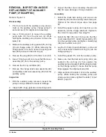
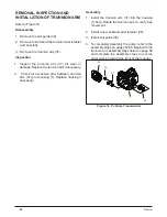
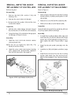
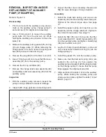
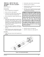
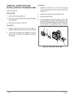
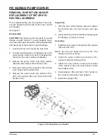
Refer to Figure 3.
Disassembly
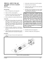
1. Remove the fan shroud (210) from the mounting
bracket (209) by carefully pushing down on the
shroud tabs.
2. Remove the nut (106) and fan assembly (90).
3. Remove the bolts (10) and bracket (209).
Inspection
Inspect the fan shroud (210), fan assembly (90) and
mounting bracket (209) for damage.
Assembly
1. To install the mounting bracket (209), align and
insert the bolts (10) into the bracket and charge
pump cover. While holding the charge cover in
place, tighten the bolts (10) per table 2, page
74.
2. Install the fan and washer assembly onto the
shaft.
3. Install the nut (106) and tighten per table 2, page
74.
4. Install the fan shroud (210) onto the mounting
bracket (209). Make sure that all shroud lock
tabs are fully engaged in the mounting bracket
slots.
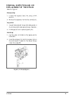
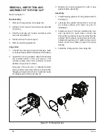
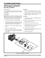
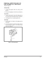
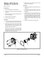
Figure 2. PK Pump Standard Control Arm
Figure 3. PK Pump Fan Assembly
Refer to Figure 2.
Disassembly
1. Remove the bolt (106), washer (104) and
bushing (101).
2. Remove the outer control arm bracket.
3. Remove bolt (103), washer (104) and the inner
control arm bracket.
Inspection
1. With the arm control linkage removed, inspect
the trunnion arm (37) and trunnion arm seal (49).
2. Inspect bushing (101) and all other linkage parts
for damage, corrosion or wear.
Assembly
1. Install the inner control arm bracket, washer
(104) and bolt (103).
NOTE: Do not over tighten the bolt (103). The
bracket must move freely.
2. Install the outer control arm bracket, bushing
(101), washer (104, and bolt (106). Tighten to
the correct torque value. See page 74.
209
10
106
90
210
Summary of Contents for HGM-H Series
Page 1: ...BLN 0043 January 2018 HGM H Series Motor Service and Repair Manual ...
Page 25: ...24 HGM H HGM H MOTOR EXPLODED VIEW ...
Page 29: ...HEMTM Series Motor Service and Repair Manual BLN 0083 January 2018 ...
Page 52: ...PRM MOTOR Service and Repair Manual ...
Page 56: ...PRM 3 EXTERNAL FEATURES PRM MOTOR Figure 1 PRM External Features ...
Page 77: ...24 PRM SECTION 8 PARTS LIST Figure 48 MA04K030 ...
Page 81: ...BLN 50231 January 2018 BDP 10L PL Hydrostatic Pump Service and Repair Manual ...
Page 82: ......
Page 83: ......
Page 84: ......
Page 85: ......
Page 86: ......
Page 87: ......
Page 88: ......
Page 89: ......
Page 90: ......
Page 91: ......
Page 92: ......
Page 95: ......
Page 96: ......
Page 97: ......
Page 98: ......
Page 99: ......
Page 100: ...HGM 12P LSHT Wheel Motor Service and Repair Manual BLN 52197 January 2018 ...
Page 102: ...2 Exploded view HGM P ...
Page 117: ...HGM E LSHT Wheel Motor Service and Repair Manual BLN 52198 January 2018 ...
Page 144: ...2 P Series EXTERNAL FEATURES PC SERIES Figure 1 PC Pump with Standard Charge Pump ...
Page 146: ...4 P Series EXTERNAL FEATURES PJ SERIES Figure 3 PJ Pump with Standard Charge Pump ...
Page 147: ...5 P Series Figure 4 PK Pump With Standard Charge Pump EXTERNAL FEATURES PK SERIES ...
Page 176: ...34 PC Series Figure 16 PC Pump BOXES INDICATE ITEMS INCLUDED IN Kit Number ...
Page 192: ...52 PG PE Series Figure 17 PG PE Pump BOXES INDICATE ITEMS INCLUDED IN KITS Kit Number ...
Page 208: ...70 PJ Series Figure 17 PJ Pump BOXES INDICATE ITEMS INCLUDED IN Kit Number ...
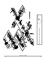
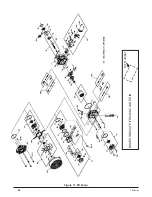
Page 224: ...88 PK Series Figure 17 PK Pump BOXES INDICATE ITEMS INCLUDED IN Kit Number ...
Page 240: ...106 PR Series Figure 17 PR Pump BOXES INDICATE ITEMS INCLUDED IN KITS Kit Number ...
Page 261: ...HGM C LSHT Wheel Motor Service and Repair Manual BLN 52690 January 2018 ...

