background image

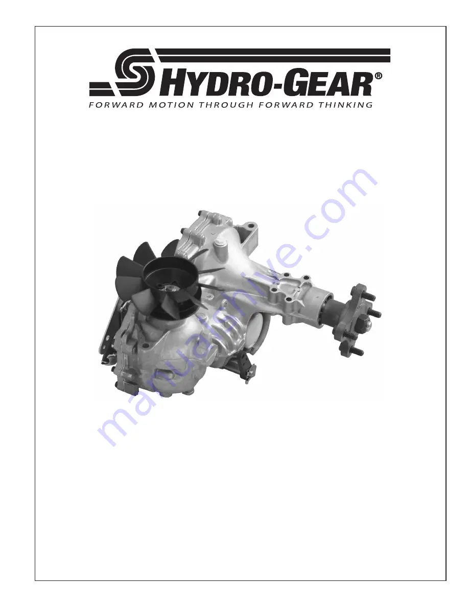
ZT-2800

®

/ZT-3100™/ZT-3400™

Integrated Zero-Turn Transaxle

Service and Repair Manual

BLN-52441

February 2011

Summary of Contents for ZT-2800

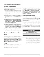
Page 1: ...ZT 2800 ZT 3100 ZT 3400 Integrated Zero Turn Transaxle Service and Repair Manual BLN 52441 February 2011 ...

Page 2: ...sembly 15 Parking Brake Adjustment 16 Parking Brake Assembly 17 Brake Arm Assembly 18 Hub Removal 19 Tear Down and Reassembly 20 How To Use This Manual 20 General Instructions 20 Tools 21 Torques 21 Transaxle Removal 22 Fan and Pulley 22 24 Side Cover 25 Bull Pinion and Reduction Gears 26 Charge Pump 27 Input Shaft 28 Bypass Arm 29 Swashplate 30 Center Section 31 Brake Assembly 32 33 Center Sectio...

Page 3: ... It is necessary and a good shop practice that your service area be equipped with the proper tools and the mechanics be supplied the latest information available All repair procedures illustrated in this guide are suggested but pre ferred methods of repair Internal repair procedures require that the transaxle unit be removed from the vehicle This is not a certification test or study guide for a ce...

Page 4: ...n formation useful in servicing the Hydro Gear ZT 2800 ZT 3100 and ZT 3400 Integrat ed Zero Turn Transaxles This manual includes the general descriptions hydraulic schematics technical specifications servicing and trouble shooting procedures for both transaxles Other than recommended oil and filter changes the transaxle normally will not require servic ing during the life of the vehicle in which i...

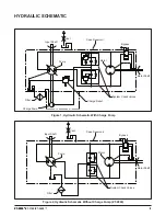
Page 5: ...Pump ZT 2800 HYDRAULIC SCHEMATIC Figure 1 Hydraulic Schematic With Charge Pump Vent Vent Bypass Motor Shaft Motor Pump Filter Charge Pump Charge Relief System Check Valves Input Shaft Case Reservoir Motor Shaft System Check Valves Input Shaft Filter Pump Motor Bypass Case Reservoir ...

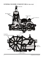
Page 6: ... 3100 ZT 3400 EXTERNAL FEATURES ZT 2800 ZT 3100 ZT 3400 similar Axle Shaft Main Housing Control Arm Top View Parking Brake Arm Side Cover Bypass Arm Inboard View Drain Port For Horizontal Installation Top Port Plug ...

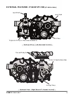
Page 7: ...RES ZT 2800 ZT 3100 ZT 3400 similar Outboard View Left Standard Control Outboard View Right Return To Neutral Control Input Shaft Oil Filter Axle Shaft Expansion Port For Horizontal Installation Charge Pump Return To Neutral Assembly Fan and Pulley Kit ...

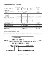
Page 8: ... m 200 lb ft 270 N m Weight on Tires per unit Maximum with 18 tires Maximum with 20 tires Maximum with 22 tires Maximum with 23 tires 400 lb 181 kg 360 lb 163 kg 480 lb 217 kg 440 lb 199 kg 400 lb 181 kg 540 lb 244 kg 480 lb 217 kg 440 lb 199 kg 650 lb 295 kg 625 lb 283 kg 600 lb 272 kg Axle Shaft Diameter 1 00 in 25 4 mm 1 125 in 28 5 mm Axle Shaft End Options Tapered 4 Bolt Flange Tapered 4 Bolt...

Page 9: ...nvolving the equipment or the performance of your job Never allow untrained or unauthorized person nel to service or repair the equipment Wear appropriate clothing Loose or hanging clothing or jewelry can be hazardous Use the appropriate safety equipment such as eye and hearing protection and safety toe and slip proof shoes Never use compressed air to clean debris from yourself or your clothing To...

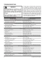
Page 10: ...pring Unit Is Noisy Oil level low or contaminated oil Fill to proper level or change oil Page 11 Excessive loading Reduce vehicle loading Page 9 Loose parts Repair or replace loose parts Bypass assembly sticking Repair or replace linkage Page 9 Air trapped in hydraulic system Purge hydraulic system Page 12 Brake Partially Engaged Disengage Brake Replace Broken or Missing Brake Return Spring Unit H...

Page 11: ...ive belt idler pulley s and idler spring s Insure that no belt slip page can occur Slippage can cause low input speed to the transaxle 4 Inspect the vehicle control linkage to the directional control arm on the transaxle Also insure that the control arm is securely fas tened to the trunnion arm of the transaxle 5 Inspect the bypass mechanism on the transaxle and the vehicle linkage to insure that ...

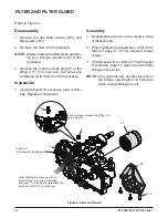
Page 12: ...ssembly 1 Reassemble all parts in the reverse order of disassembly 2 When tightening the fasteners refer to the table on page 21 for the required torque values 3 Fill transaxle with oil Refer to Fluid Change Procedures page 11 steps 3 and 4 for filter change instructions NOTE As a general rule use the low end of the torque specification on fasteners when reassembling the unit Figure 4 Filter and G...

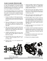
Page 13: ...s Torque screws to 65 in lbs 7 3 Nm each 6 Repeat steps 1 5 on the opposite side transaxle drive 7 Drain old oil filters of all free flowing oil prior to disposal Place used oil in appropriate containers and deliver to an approved re cycling collection facility 8 Remove the top port plug figure 6 from the left side and right side transaxles prior to filling with oil This will allow the transaxles ...

Page 14: ... to the specifi cations outlined in this manual The following procedures are best performed with the vehicle drive wheels off the ground Then repeated under normal operating condi tions If this is not possible then the procedure should be performed in an open area free of any objects or bystanders 1 Disengage the brake if activated 2 With the bypass valve open and the engine running slowly move th...

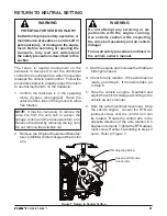
Page 15: ...ing mode bypass disengaged Raise the vehicle s drive tires off the ground to allow free rotation NOTE It may be necessary to remove the drive tire from the axle hub to access the linkage control and the transaxle return arm Remove the wheel by removing the lug nuts Do not remove the axle hub nut 2 Remove the Original Equipment Manufac turer s OEM s control linkage at the control arm 3 Start the en...

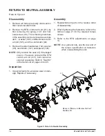
Page 16: ...The seal is not part of the RTN control arm kit 211 and cannot be serviced separately Refer to Seal Kit in the Items List on pages 43 or 45 Inspection 1 Inspect all parts for excessive wear or dam age Replace if necessary Assembly 1 Reassemble all parts in the reverse order of disassembly 2 When tightening the fasteners refer to the table on page 21 for the required torque values 3 Refer to the RT...

Page 17: ... be serviced separately Refer to Seal Kit in the Items List on pages 43 or 45 Inspection 1 Inspect all parts for excessive wear or dam age Replace if necessary Assembly 1 Reassemble all parts in the reverse order of disassembly with the exception of the washer 45 and the lock nut 47 NOTE Discard the washer 45 and the lock nut 47 2 When tightening the fasteners refer to the table on page 21 for the...

Page 18: ...e s actu ated position 7 Attach the retaining clip 103 to the brake cam shaft 8 Connect the vehicle parking brake linkage to the brake handle 102 9 Test the parking brake to assure it meets the vehicle manufacturer s specifications 10 It is also important to assure that the park ing brake is not partially engaged while the vehicle is in the normal drive mode This can be confirmed by moving the veh...

Page 19: ... 4 Remove the brake handle 102 5 Remove the hex head screws 105 and the cam stop retainer 104 Figure 12 Parking Brake Inspection 1 Inspect all parts for excessive wear or dam age Replace if necessary 2 Inspect the splines on the handle and brake cam shaft Assembly 1 Reassemble all parts in the reverse order of disassembly 2 When tightening the fasteners refer to the table on page 21 for the requir...

Page 20: ...ry im portant 2 Remove the retaining clip 103 3 Remove the brake arm 102 Inspection 1 Inspect all parts for excessive wear or dam age Replace if necessary 2 Inspect the splines on the brake arm and brake shaft Assembly 1 Reassemble all parts in the reverse order of disassembly Figure 13 Parking Brake Character 7 in the model number code 3 Example ZX XXXX 3XXX XXXX Brake Shaft 101 Brake Arm 102 Ref...

Page 21: ...the OFF position chock the front wheels engage the parking brake Raise the vehicle drive tires off the ground and remove the lug nuts from the vehicles drive wheel hub studs 2 Remove the hex retaining nut 3 4 16 from the center of the axle hub and discard 3 Back out the hub removal tool bolt with a 1 1 8 socket before installing the hub re moval tool to the axle hub HUB REMOVAL 4 Insert the hub re...

Page 22: ...hemicals Protect all exposed sealing surfaces and open cavities from damage and foreign material The external surfaces should be cleaned before beginning any repairs Do not use a pressure washer to clean the transaxle Upon removal it is recommended that all seals O rings and gaskets be replaced During installation lightly lubricate all seals O rings and gaskets with a clean petroleum jelly prior t...

Page 23: ...k Plug or Shock Valve 280 400 lb in 31 6 45 2 Nm Center Section 25 Check Plug or Shock Valve 280 400 lb in 31 6 45 2 Nm Center Section 27 Screw Hex Head 3 8 16 x1 5 525 700 lb in 59 3 79 1 Nm Center Section Screws 42 Stud Short 5 16 24 50 120 lb in 5 6 13 5 Nm Control Arm 46 Torx Head Screw 5 16 24 x 1 00 230 310 lb in 25 9 35 0 Nm RTN FR Control Arm 99 Nut Patch Lock 3 4 16 240 260 lb ft 325 4 35...

Page 24: ...mbly is accomplished by performing the Assembly portions of the procedures If the unit has been completely disassembled a summary of the assembly procedures in the order in which they should occur is given on page 38 Figure 15 Fan Pulley Kit 207 Configuration A Refer to Figure 15 Disassembly FAN AND PULLEY KIT 207 CONFIGURATION A 1 Remove the locknut 122 slotted washer 123 fan 120 and the pulley 1...

Page 25: ...Fan Pulley Kit 207 Configuration B Figure 17 Fan Pulley Kit 207 Configuration C Refer to Figure 16 FAN AND PULLEY KIT 207 CONFIGURATION B 1 Remove the locknut 122 and detach the fan and pulley assembly from the input shaft 2 Separate the assembly by removing the screws 123 fan 120 and the pulley 121 Inspection 1 Check all components for excessive wear or damage Replace if necessary Assembly 1 Reas...

Page 26: ...n 1 Check all components for excessive wear or damage Replace if necessary 2 Inspect input shaft splines for wear or dam age Assembly 1 Reassemble all parts in the reverse order of disassembly 2 When tightening the fasteners refer to the table on page 21 for the required torque values NOTE As a general rule use the low end of the torque specification on fasteners when reassembling the unit Figure ...

Page 27: ...xle avoiding any debris from entering the hous ing SIDE COVER Figure 19 Side Cover Inspection 1 Inspect the bearing and bushing areas in the side cover for excessive wear or damage Replace if necessary Assembly 1 Apply a bead of sealant around the perim eter of the main housing face See Sealant Application Diagram on page 38 2 Install the locating pins if not already in stalled 3 Install the side ...

Page 28: ...l splines for wear or damage 2 Separate the reduction gears and inspect the gears and jack shaft pin for excessive wear or damage Replace if necessary BULL PINION AND REDUCTION GEARS Assembly 1 Install the washer 74 pinion gear 72 and secure their placement with retaining ring 71 onto the motor shaft 73 2 Install the washer 70 onto the motor shaft 73 3 Install the spacer 109 and the bull gear 91 o...

Page 29: ...wear or damage Replace if necessary Assembly 1 Reassemble all parts in the reverse order of disassembly NOTE When reinstalling the charge pump components replace the O ring 132 Also replace the connecting tubes 130 and lip seal 157 if they have been removed 2 Align the mark on the charge pump cover from step 1 Disassembly with the mark on the main housing Figure 21a Charge Pump 3 When tightening t...

Page 30: ...neoprene head hammer the shaft from the charge pump side of housing Care Figure 22 Input Shaft should be taken not to damage the shaft or gerotor running surface Remove the bearing from pump shaft only if worn or damaged 5 Remove the wire ring retainer 54 and the bearing 53 from the pump shaft 52 Inspection 1 Inspect the bearing and input shaft for wear or damage Inspect the splines on the shaft f...

Page 31: ...ot necessary to remove the clip retaining ring 31 from the bypass rod 32 unless it is damaged or worn 5 Remove the lip seal 30 and discard Inspection 1 Inspect the bypass rod 32 for wear or dam age Replace if necessary NOTE Take care to insure that the bypass rod is free of burrs that may cut the rubber lip seal BYPASS ARM Assembly 1 Install a new lip seal 30 2 Install the clip retaining ring 31 a...

Page 32: ...ning surface Inspection 1 Inspect the swashplate 40 and thrust bearing assembly 65 for wear or damage Replace if necessary 2 Inspect pump block per detail on page 32 Assembly 1 Reassemble all parts in the reverse order of disassembly 2 Apply a light coating of oil to running sur faces on center section swashplate bearing races thrust bearing assembly and pump block assembly 3 Place the thrust bear...

Page 33: ...r or damage 2 Inspect the motor shaft for wear or damage Replace if necessary 3 Inspect for scratches on the machined sur faces of the center section 4 Inspect motor cylinder block assembly 64 per detail on page 35 Assembly 1 Reassemble all parts in the reverse order of disassembly 2 Apply a light coating of oil to all running surfaces on the center section 3 Place the thrust bearing assembly 60 i...

Page 34: ... 1 Inspect all components for unusual wear or damage Assembly 1 Install the new O rings 10 onto the brake cam shaft 101 NOTE Apply a thin coating of oil to the O rings before installing To protect the O rings from possible damage during installation apply a protective covering over the splines of the brake cam e g cellophane tape etc 2 Place the brake puck 100 onto the brake cam shaft 101 Install ...

Page 35: ...or unusual wear or damage Assembly 1 If removed install brake pawl on brake shaft Refer to figure 29 for orientation NOTE Apply a thin coating of oil to the O rings before installing To protect the O rings from possible damage during installation apply a protective covering over the splines of the brake shaft e g cellophane tape etc 2 Install the new O rings 10 onto the brake shaft 101 Figure 28 B...

Page 36: ...pin to slide out Use caution when relieving spring force Inspect the center section at the charge seat for wear or damage NOTE The check ball should seat properly in the check seat Inspection 1 Inspect all components for unusual wear or damage Pay particular attention to the cen ter section s threaded ports and passages there must be no lose particles or debris Assembly 1 Install the charge relief...

Page 37: ...inder block assemblies before reassembly After reassembling the cylinder block compo nents set aside until ready for installation of the center section and swashplate Refer to pages 30 and 31 Figure 31 Plug Seal 26 Refer to Figure 31 In order to gain access to the check plugs 24 25 it is necessary to remove the plug seals 26 This is accomplished by inserting a seal hook or puller into and through ...

Page 38: ...axle shaft only if worn or damaged Inspection 1 Inspect the splines on the axle shaft for wear or damage Replace if necessary 2 Inspect the bearing 95 for wear or damage Replace if necessary Assembly 1 Assemble items in reverse order of disas sembly NOTE To protect the lip seal from possible damage when installing into the bore and over the axle shaft apply a protec tive covering over the splines ...

Page 39: ...bearing from the axle shaft only if worn or damaged Inspection 1 Inspect the splines on the axle shaft for wear or damage Replace if necessary 2 Inspect the bearing 95 for wear or damage Replace if necessary Assembly 1 Assemble items in reverse order of disas sembly NOTE To protect the lip seal from possible damage when installing into the bore and over the axle shaft apply a protec tive covering ...

Page 40: ...ee page 27 6 Install the reduction gears pinion gear and bull gear See page 26 Figure 35 Sealant Application Diagram ASSEMBLY AFTER A COMPLETE TEAR DOWN 7 Apply sealant to the main housing and cen ter section prior to installing the side cover See page 25 and diagram below NOTE Prior to applying the new sealant the old sealant must be removed from all surfaces A small consistent bead approx 1 16 1...

Page 41: ...ing sequence diagram Starting with the number 1 screw location tighten sequentially through to 16 Torque each screw to 105 155 lb in 11 87 17 52 Nm NOTE As a general rule use the low end of the torque specification SIDE COVER SCREW TIGHTENING SEQUENCE ...

Page 42: ...n Pos Control Side Type Control Arm Bypass Arm Fan Pulley Kit Breather Fittings Reserved On page 1 of the service schematic locate the part item number that you want to find the 3 part number for In this example we ll use item number 81 Gear Proceed through the schematic pages until you see an illustration of the part 4 Match the item number on the illustrated part to the item number listed in the...

Page 43: ...ZT 2800 ZT 3100 ZT 3400 41 Notes ...

Page 44: ...00 ZT 3400 ZT 2800 ZT 3100 TRANSAXLE EXPLODED VIEW ITEMS NOT SHOWN 13 Sealant 14 Oil 20W50 70 3 oz 200 Seal Kit 209 Hub Puller Seal Kit contains item s 10 26 30 31 33 35 41 46 56 57 71 90 96 103 130 132 156 157 and 166 ...

Page 45: ...ar Pinion 16T 14T 13T 73 Shaft Motor 74 Washer 72 x 1 16 x 04 80 Washer 5 x 1 0 x 03 81 Gear Reduction 43T 45T 46T 82 Gear Reduction 11T 83 Pin Jack Shaft 90 Ring Retaining 2 06 Internal 91 Gear Bull 54T 92 Spacer 750 x 1 000 x 257 93 Bearing Ball 75 x 40 x 12 94 Shaft Axle 95 Bearing Ball 1 0 x 52 x 15 Open 6205M 96 Seal Lip 25 x 52 x 10 TC Gray 97 Hub 99 Nut Patch Lock 3 4 16 100 Pawl Brake 101 ...

Page 46: ...ZT 3100 ZT 3400 ZT 3400 TRANSAXLE EXPLODED VIEW ITEMS NOT SHOWN 13 Sealant 14 Oil 20W50 70 3 oz 200 Seal Kit 209 Hub Puller Seal Kit contains item s 6 10 26 30 31 33 35 41 46 54 56 57 71 90 96 103 130 132 and 157 ...

Page 47: ... Gear Pinion 16T 14T 13T 73 Shaft Motor 74 Washer 72 x 1 16 x 04 80 Washer 5 x 1 0 x 03 81 Gear Reduction 45T or 46T 82 Gear Reduction 11T 83 Pin Jack Shaft 90 Ring Retaining 2 06 Internal 91 Gear Bull 54T 92 Spacer 750 x 1 320 x 257 93 Bearing Ball 75 x 40 x 12 94 Shaft Axle 95 Bearing Ball 96 Seal Lip 97 Hub 99 Nut Patch Lock 3 4 16 100 Pawl Brake 101 Shaft Brake 102 Handle Brake 103 Clip Retain...

Page 48: ...rimary function is to limit pressure in the charge circuit Check Valve A valve whose primary function is to restrict flow in one direction Closed Loop A sealed and uninterrupted circulating path for fluid flow from the pump to the motor and back Decay Rate The ratio of pressure decay over time Entrained Air A mechanically generated mixture of air bubbles having a tendency to separate from the liqu...

Page 49: ...id into all of the components and allowing the air a path of escape Rated Flow The maximum flow that the power supply system is capable of maintaining at a specific operating pressure Scoring Scratches in the direction of motion of mechanical parts caused by abrasive contami nants Swash Plate A mechanical device used to control the displacement of the pump pistons in a fluid power system System Ch...

Page 50: ...48 ZT 2800 ZT 3100 ZT 3400 Notes ...

Page 51: ...ZT 2800 ZT 3100 ZT 3400 49 Notes ...

Page 52: ... 2011 HYDRO GEAR Printed in U S A Rev P12 ...

Reviews: