ZT-2800
®
/ZT-3100/ZT-3400™
31
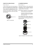
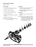
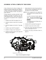
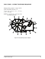
CenTer seCTiOn
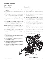
figure 26, Center section
Refer to Figure 26
disassembly
1. Requires removal of all items beginning on
page 14.
2. Remove the center section mounting screws
(27).
3. Remove the center section, the motor shaft
(73), the motor cylinder block assembly (64)
and the brake shaft (101) as a single item.
4. Remove the motor cylinder thrust bearing
(60).
5. Remove the motor cylinder block assembly
(64) from the motor shaft (73). Remove the
motor shaft (73) from the center section.
NOTE:
A bypass puck is located beneath the
motor cylinder block assembly. See
item 22, page 34.
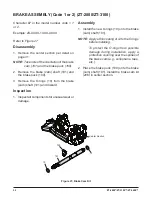
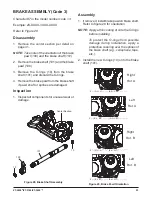
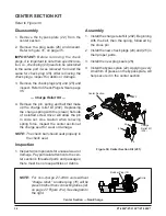
6. Remove brake shaft assembly (101) and
set aside. Refer to figures 27-28, pages
32-33.
inspection
1. Inspect the races of the thrust bearing (60)
for wear or damage.
2. Inspect the motor shaft for wear or damage.
Replace if necessary.
3. Inspect for scratches on the machined sur-
faces of the center section.
4. Inspect motor cylinder block assembly (64)
per detail on page 35.
assembly
1. Reassemble all parts in the reverse order
of disassembly.
2. Apply a light coating of oil to all running
surfaces on the center section.
3. Place the thrust bearing assembly (60) into
the main housing (1).
4. Place the motor shaft (73) into the center
section. Slide the motor block assembly (64)
onto the motor shaft (73) so that the pistons
are facing the thrust bearing (60).
5. Install the brake shaft assembly (101), if not
already installed. Refer to figures 27-28,
pages 32-33.
6. Align the assembled components (center
section, the motor block and shaft, and the
brake shaft assembly) with the main housing
and install.
7. Install the center section mounting screws
(27) to the proper torque.
1
73
Center Section
27
27
27
101
60
64


