Up-Flo
®
Filter Operation and Maintenance Manual
Recommended Equipment
•
Safety Equipment (traffic cones, etc.)
•
Crow bar to remove grate or lid
•
Pole
with skimmer or net (if floatables removal is not to be
done with vactor hose)
•
Sediment probe (such as a Sludge-Judge
®
)
•
Vactor truck (flexible hose preferred)
•
OSHA Confined Space Entry Equipment
•
Up-Flo
®
Filter Replacement Media Packs (available from
Hydro International)
•
Hydro International Up-Flo
®
Filter Maintenance Log
•
Screwdriver (flat head)
•
Replacement Drain Down Filter components supplied by
Hydro International
Maintenance Procedures Requiring Man Entry:
Media Pack and Drain Down Filter Replacement Procedures
1.
Follow Floatables and Sump Cleanout Procedures, 1 – 13.
2.
Following OSHA Confined Space Entry procedures, enter the
Up-Flo
®
Filter Chamber.
3.
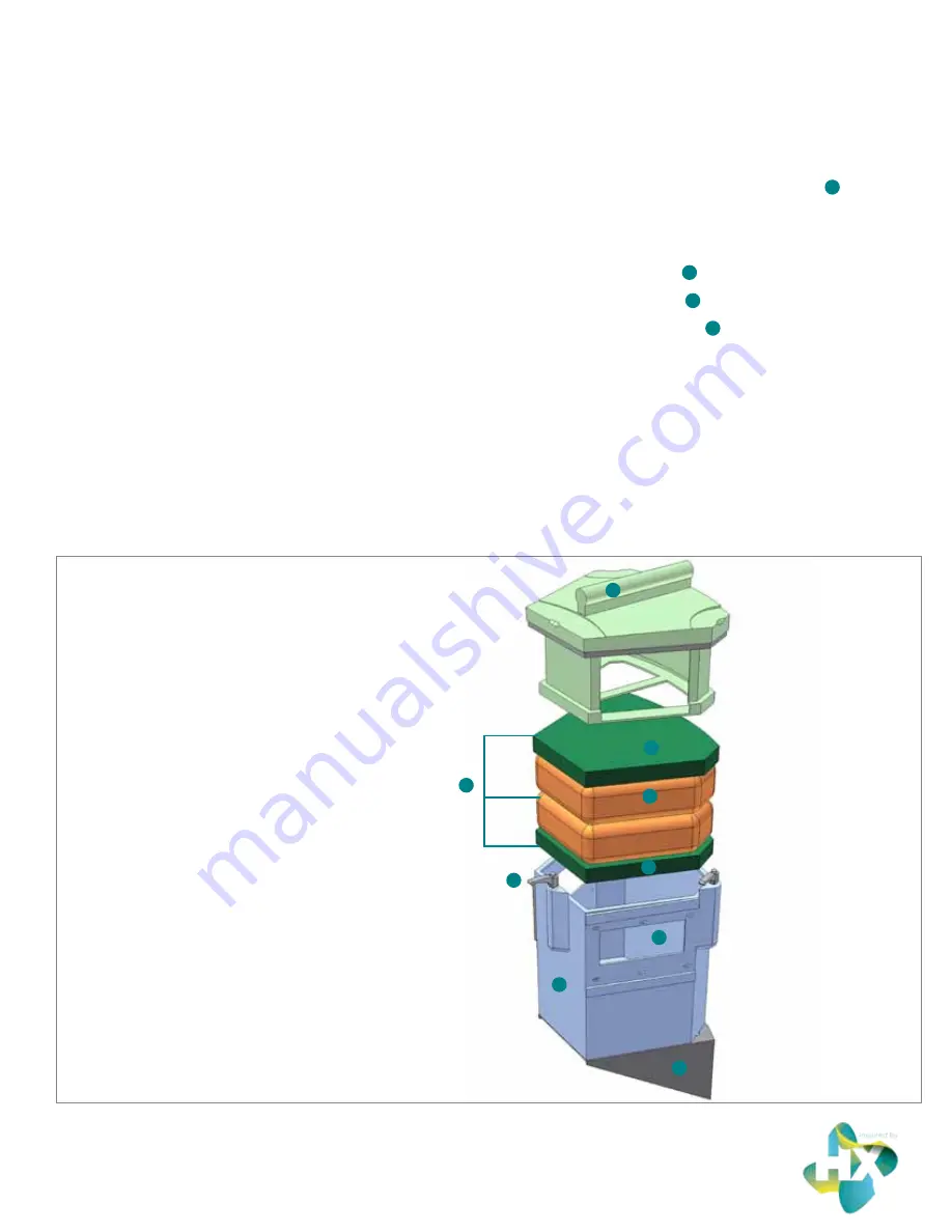
Open the Filter Module by turning the three cam latches on
the front and sides of the module. Remove the lid
1
to gain
access to the Media Pack (Fig.9).
4.
Remove and discard the spent Media Pack. The Media Pack
contents include:
• A top layer of green
2
Flow Distributing Media.
• Two (2) Media Bags
3
equipped with nylon handles.
• A bottom layer of green
2
Flow Distributing Media.
5.
Insert a new Media Pack, supplied by Hydro International.
• First, insert a bottom layer of green Flow Distributing
Media. Be sure that the media sits snugly and level at
the bottom of the Filter Module.
• Next, insert the first of two (2) replacement Media
Bags. Smooth the bag out with your hands to make
sure that the bag extends snugly to the walls and
corners of the Filter Module.
• Insert the second Media Bag, following the
same procedure.
Fig.9 The Filter Module houses the Media Restraint and the Media Pack.
1. Filter Module Cover and Media Restraint
2. Flow Distributing Media
3. Filter Media Bags
4. Replaceable Media Pack
5. Cam Latch
6. Conveyance Channel
7. Filter Module
8. Support Bracket / Angled Screen
5
7
1
3
4
2
6
8
2
Page | 11


