124
fi
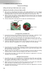
g. 8.64
fi
g. 8.65
fi
g. 8.66
8 - A
ਢਢਤਲਲਮਨਤਲ
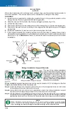
Cantilever reinforcement cable retainer
The optional cantilever reinforcement cable retainer is used when longer cantilevers are
required on an installation. Whereas the total loads permitted in a confi guration must
usually be concentrated close to the motorized unit, the bridge reinforcement cables and
the retaining device allow the distribution of the loads over the entire length of the cantilever,
thus increasing load capacity at the end of the cantilever.
(optional)
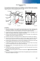
Guide shoe on
cable retainer
Top cable
retainer bracket
Cable retainer
post
Top cable retainer
bracket with post
Safety guidelines
1-
The use of a cantilever reinforcement cable retainer installation is not allowed on
freestanding confi gurations.
2-
When a reinforcement cable retainer is used in a cantilever setup, the top cable
retainer bracket must never be above the last tie level installed.
3-
The use of equipment or accessories may not allowed in combination with the use of a
cantilever reinforcement cable retainer. For more information about the combined use
of equipment and accessories in an installation, refer to the tables for the combinations
allowed or restricted in linked and unlinked confi gurations on p. 17 and p. 18 of
the
Motorized Unit
section.
4-
For more information on the maximum number of bridges allowed for installations
using cantilever reinforcement cable retainers, refer to p. 106 and p. 107 of the
Load Capacities
section.
5-
On an installation using a cantilever reinforcement cable retainer, the
maximum number
of workers allowed on the whole length of bridge supported by the cables is two
.
6-
A motorized unit equipped with a cantilever reinforcement cable retainer
must be
brought down to base level when not in use
.
Installation
1-
Make sure that the cables are in good condition, free of kinks, twists, etc.
2-
Make sure that the motorized unit has been installed following the installation guidelines
starting on p. 17 of the
Motorized Unit
section and that it can be operated safely. It
is
mandatory
to
pre-install all tie levels
up to the top of the work
before
installing
the optional cantilever reinforcement cable retainer.
3-
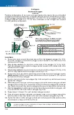
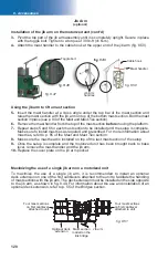
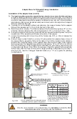
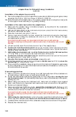
Remove one of the two guide shoes (fi g. 8.65) located on the top cable retainer bracket
(fi g. 8.66).
4-
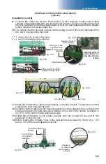
Position the bottom of the post of the cable retainer in the middle of the top tube on
the main trolley (fi g. 8.70).
5-
Re-install the guide shoe removed in step 2.
6-
Using a 5/8" x 6 1/2" bolt, attach the post of the cable retainer to the top tube on the
main trolley. It may be required to change the angle of the hydraulic hose that is close
to the top tube of the main trolley to allow the positioning and bolting of the cable
retainer (fi g. 8.67, p. 125).
7-
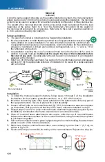
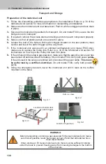
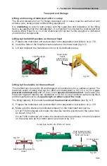
Run the connecting cables for the two limit switches of the cantilever reinforcement
cable retainer through the structure of the main trolley up to the control panel, making
sure the cables remain clear of any moving parts.
8-
Locate the
TOP LIMIT
and
TOP F. LIMIT
ports under the control panel. Unplug the cables
connected to these two ports, making sure they are properly labeled according to their
function.
n
n
n
n
n
n
WARNING
On an installation using a cantilever reinforcement cable retainer, the
maximum number of
workers allowed on the whole length of the bridge supported by the cables is
two
. When a
cantilever reinforcement cable retainer is used on an
unlinked setup
, the
maximum length
of
cantilever allowed is 25' (7,6 m).

