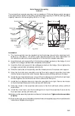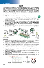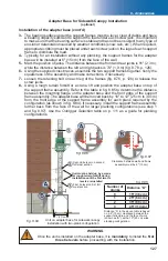
125
fi
g. 8.71
fi
g. 8.72
fi
g. 8.73
fi
g. 8.74
fi
g. 8.67
fi
g. 8.68
fi
g. 8.69
fi
g. 8.70
fi
g. 8.7
8 - A
ਢਢਤਲਲਮਨਤਲ
Cantilever reinforcement cable retainer
(optional)
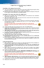
Installation (cont'd)
9-
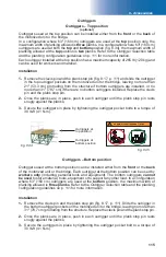
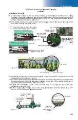
Connect the cables for the two limit switches of the cantilever reinforcement cable
retainer in the appropriate port, according to their function. Test the operation of each of
the limit switches by placing a metal object in front of it and make sure that the display
screen indicates the proper detection.
10-
The cables must be secured in place with tie wraps to avoid any risk of damage when
the unit is moving along the mast.
TOP LIMIT
port
TOP F. LIMIT
port
11-
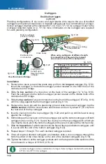
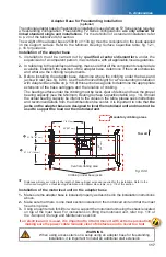
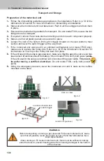
Install the turnbuckles, cables and shackles on the top bracket. Turnbuckles must be
extended to their maximum length.
12-
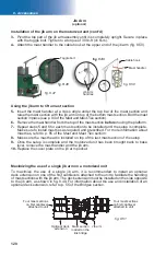
Install the bottom cable retainer bracket against the center diagonal brace of the fourth
bridge and attach the cable shackles (installed at one end of the cables, as shown in
fi g. 8.74) to the bottom cable retainer bracket.
13-
Adjust the turnbuckles so the cables become only taut enough for the end of this
cantilever to begin to rise.
14-
Before loading the bridges, refer to the appropriate load capacity charts on p. 106
and p. 107 of the
Load Capacities
section.
Fourth bridge
of cantilever
assembly
Shackles
on bottom
cable retainer
bracket
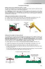
Top cable retainer
bracket
Bearing point of
cable retainer on
top tube of main
trolley
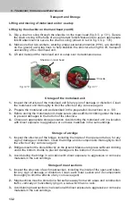
Bottom of post of
cable retainer
Area on top tube of main trolley where
post of cable retainer will be attached
Attachment bolt will be
installed through here
Attachment bolt
The angle of this
hydraulic hose
may have to be
adjusted


