85
fi
g. 6.3
6 - M
ਠਲਲ਼
ਠਭਣ
M
ਠਲਲ਼
T
ਨਤਲ
Mast sections
Removal and transport of mast sections
Loading mast sections on the platform
1-
Remove the mast head (fi g. 6.2, p. 84).
2-
Remove the bolt assemblies on all four corners.
3-
Using an optional jib arm (see p. 119 of the
Accessories
section) or any other appropriate
lifting device such as a crane or a rough terrain forklift, lift the mast section to be removed.
If mast sections must be stored on the platform, refer to the loading instructions above.
4-
Mast sections can be removed and carried in pre-assembled lengths (also referred
to as “sticks”). It is recommended to use an optional multiple mast handler to handle
pre-assembled lengths of mast sections. For instructions on the use of the optional
mast handler, refer to p. 116 of the
Accessories
section.
5-
Mast sections must be stored on a fl at surface away from work areas and construction
traffi c, vertically or horizontally, lying on a side which has no rack.
Mast Ties
General guidelines
1-
Freestanding confi gurations are not allowed for F2 Series motorized units unless an
optional adapter base for freestanding installation is used. For instructions on the
installation and use of an optional adapter base for freestanding installation, refer to
p. 117 of the
Accessories
section.
2-
The pre-installation of mast ties consists in the installation of all mast sections and
tie levels necessary to reach the full height of the mast, as required and allowed,
before beginning normal operation of the setup
. The pre-installation of tie levels
is mandatory for all F2 Series installations. Only a
single unit standard installation
can be installed using a progressive method of installation of tie levels. For more
information about methods of installation and standard installations, refer to p. 20
of the
Motorized Unit
section.
3-
Determine the mast tie components and the quantity required of each according to the
installation method appropriate for the installation, the number of planks required and
allowed for the confi guration and the height of the mast. For more information about
methods of installation, see p. 20 of the
Motorized Unit
section.
4-
Determine the
location of perpendicular mast ties
according to the confi guration.
For instructions on how to determine the location of perpendicular mast ties, refer to
p. 88 of this section.
Optional deck
extension
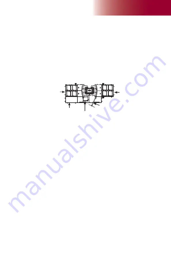
Mast section loaded on
the link bridge
Four mast sections
on fi rst cantilever
attached to unit
Four mast sections
on fi rst cantilever
attached to unit
1-
Mast sections can be loaded on the platform using an optional jib arm, a crane or a
rough terrain forklift (see p. 119 of the
Accessories
section for more information on
the installation and use of the jib arm).
2-
There can be up to a
maximum of four mast sections on each side of the mast at
a time
. A ninth mast section can be loaded on the link bridge of the motorized unit, as
shown in fi g. 1.32. It is recommended to install an optional deck extension on one of
the fi rst cantilevers attached to the unit to facilitate the handling of mast sections with
the jib arm. The deck extension must be installed on the side
opposite
to the jib arm,
as shown in fi g. 1.32. For information about the use and installation of an optional deck
extension, refer to p. 55 of the
Bridges
section.
3-
Mast sections must be loaded equally on either side of the mast and taken alternately
from one side, then the other when installing to ensure good balance. Refer to the
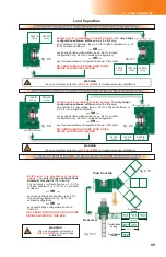
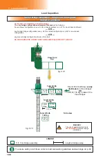
Load Capacities
section on p. 94 for more information about loading the platform.


