background image

ORBIT

®

 SPRINKLER SySTEm DESIGNER™ 

InstallatIon GuIde

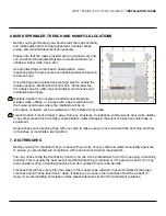
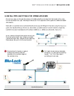
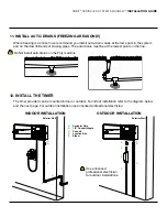
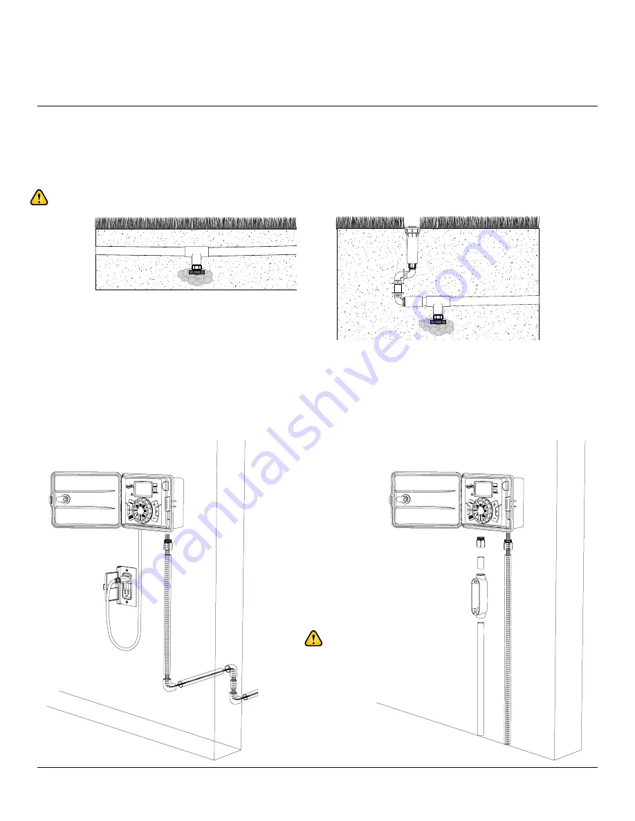
11. Install auto-dRaIns (fReezInG aReas onlY)

  Where freezing is a concern we recommend you install auto-drain valves at the low spots in the system 

and on the downhill ends of sloping pipes. The auto drains must be at the lowest points in the line.


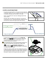
  The timer provided can be mounted indoor or outdoor. For indoor installation refer to the diagram below 

and the next page. For outdoor installation use a licensed professional electrician.

outdooR InstallatIon

exterior Wall

exterior Wall

IndooR InstallatIon

sprinkler Wire

1/2" Conduit nipple

C

 Conduit

d


Junction Box

e


Elbow

Use a licensed 
professional electrician 
for outdoor installations.

a

B

C

C

e

a

B

B

C

C

C

d

Do Not install auto-drains on the Poly mainline

12. INSTALL THE TIMER

Summary of Contents for ORBIT SPRINKLER SYSTEM DESIGNER

Page 1: ...53251 27 rA INSTALLATION GUIDE ...

Page 2: ...ic factors such as slope soil type vegetation type local climate or property peculiarities such as location of property lines utilities structures window wells stair wells fences footings foundations driveways sidewalks trees shrubs pools ponds or other physical factors which may materially affect design installation performance safety or code requirements for a sprinkler system The user is solely...

Page 3: ... 14 r Turn Water Source On 15 r r Test Each Zone 17 r Install Heads and Nozzles and Adjust Patterns 18 r Install Valve Boxes and Backfill Trenches 19 r Fine Tune Nozzles and Patterns 20 r Set Sprinkler Timer WELCOME CHECKLIST Install Poly Mainline Pipe with Insert Fittings 10 Please use the provided Checklist below as you go through the installation process to ensure you have an irrigation system ...

Page 4: ...or sprinkler systems 3 Call utility providers to mark utility lines Call before you dig in most areas dial 8 1 1 We recommend you call well in advance to give the utility companies time to mark their lines on your property The following table shows what each color represents in most areas Please consult the marking service provider or your utilities to better understand the color code used in your...

Page 5: ... REQUIRED SUPPLIES and add them to this list 5 Install Backflow prevention device and Shut off valve Check your local code to determine the backflow prevention requirements for your area You may need to hire a professional to do the installation Following are a few examples of backflow prevention devices r 4 or 5 Trenching Shovel r Trenching Machine optional r Round nosed Shovel r Latex dipped Wor...

Page 6: ...he backflow prevention This design plan does not apply to anything before this point homeowner is responsible for ensuring system complies with local codes including backflow prevention etc consult a licensed plumber before you begin A1 3 4 or 1 Poly Pipe 3 4 or 1 PVC Ball Valve Supply Line Water Flow To Manifolds We recommend that you install a 3 4 or 1 PVC Ball Valve immediately following the ba...

Page 7: ...eas Trench Caution Trench at least 2 away from any structures foundations window wells stair wells utilities or any other areas which are highly susceptible to water damage in the event of broken sprinkler lines or equipment Double check your trenching lines with your plan to make sure you have minimized the trenching and that no trenches or manifolds were forgotten 7 Dig trenches Before you dig i...

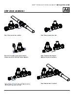
Page 8: ...tch the assembly call out with one of the following assembly drawing pages Use the assembly drawings as your guide Do not make any Poly or PVC pipe and glued connections at this point We will walk you through that in another step If A6 is called out on a Sprinkler zone Map then reference assembly A6 in the following pages for instructions on creating a drip zone valve Prepare the valve box platfor...

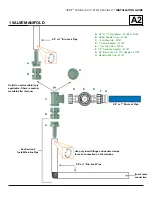
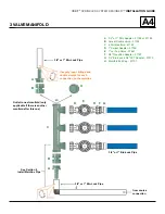
Page 9: ... 57189 B Swivel Double Union 57184 C 1 Port Manifold 57181 D 1 Swivel Adapter 57199 E 1 Jar Top Valve 57461 F 3 4 Transition Adapter 57187 G 3 4 Blu Lock x 3 4 FPT Adapter 37379 H Manifold End Cap 57197 A A B B C D D E F G H 3 4 or 1 Blu Lock Pipe Outlet to next manifold only applicable if there is another manifold after this one Use poly insert fittings and double clamps for each connection on th...

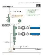
Page 10: ...61 F 3 4 Transition Adapter 57187 G 3 4 Blu Lock x 3 4 FPT Adapter 37379 H Manifold End Cap 57197 from source connection 3 4 or 1 Blu Lock Pipe See Section 9 Install Mainline Pipe Outlet to next manifold only applicable if there is another manifold after this one 3 4 or 1 Blu Lock Pipe A B H A B D D E F G 3 4 or 1 Blu Lock Pipe C Use poly insert fittings and double clamps for each connection on th...

Page 11: ...61 F 3 4 Transition Adapter 57187 G 3 4 Blu Lock x 3 4 FPT Adapter 37379 H Manifold End Cap 57197 3 4 or 1 Blu Lock Pipe A A B B C D D E F G H from source connection See Section 9 Install Mainline Pipe Outlet to next manifold only applicable if there is another manifold after this one Use poly insert fittings and double clamps for each connection on the mainline 3 4 or 1 Blu Lock Pipe 3 4 or 1 Blu...

Page 12: ...1 F 3 4 Transition Adapter 57187 G 3 4 Blu Lock x 3 4 FPT Adapter 37379 H Manifold End Cap 57197 3 4 or 1 Blu Lock Pipe 3 4 or 1 Blu Lock Pipe See Section 9 Install Mainline Pipe Use poly insert fittings and double clamps for each connection on the mainline from source connection 3 4 or 1 Blu Lock Pipe Outlet to next manifold only applicable if there is another manifold after this one B B A A B C ...

Page 13: ...emove adapter from valve Step 6 Reattach valve to manifold Step 3 Put 5 complete turns of tape around the threads of each end of the Filter Pressure Regulator Step 4 Thread the Filter Pressure Regulator into the valve until snug Step 5 Thread 1 FPT x 3 4 Blu Lock Adapter onto the Filter Pressure Regulator until snug ...

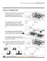
Page 14: ...rime and glue PVC pipe into the open connection on the tee and continue to the next manifold Connect the last manifold on the mainline as shown Follow the instructions above but instead of a tee you will use an elbow It is important that the mainline pipe be as deep as possible in the trenches in order to provide room for the pipes coming from each valve to the sprinkler zones A5 A5 Starting from ...

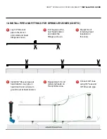
Page 15: ... along sidewalks driveways or curbs plan on spacing heads 1 to 2 from the edge or according to local code We will now step you through the process of installing the Blu Lock pipe from the heads to the valve for each sprinkler zone see Working with Blu Lock in the appendix of this guide for additional helpful information Start with one sprinkler zone and install the Blu Lock pipe and fittings for t...

Page 16: ... 2 Cut the pipe at the next head location and install the fittings as shown 3 Repeat for all remaining head locations on this zone 4 Lay 3 4 Blu Lock pipe in the trench and install end head fittings as shown Install 3 4 Blu Lock pipe at head location Lay pipe in head trench and cut pipe to ground level at head location Connect 3 4 lines using 3 4 tees and 3 4 Blu Lock pipe ...

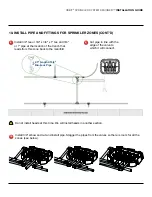
Page 17: ...nect 9 Do not install heads at this time We will install heads in another section Install 3 4 tee or 3 4 x 3 4 x 1 tee and 3 4 or 1 pipe at the location of the trench that leads from this zone back to the manifold 2 5 length of 3 4 Blu Lock Pipe Install 3 4 elbow and cut and install pipe Stagger the pipes from the valves so there is room for all the zones see below ONT D ...

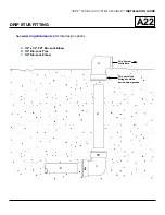
Page 18: ...tion Guide A22 Drip Stub Fitting Drip System starts here This part of the fitting should be buried below ground 3 4 x 1 2 FPT Blu Lock Elbow 3 4 Blu Lock Pipe 3 4 Blu Lock Elbow A B C A B B C See www irrigationdepot ca for drip design options ...

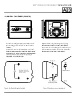
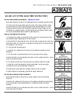
Page 19: ... line The timer provided can be mounted indoor or outdoor For indoor installation refer to the diagram below and the next page For outdoor installation use a licensed professional electrician Outdoor Installation Exterior Wall Exterior Wall Indoor Installation A Sprinkler Wire B 1 2 Conduit Nipple C Conduit D Junction Box E Elbow Use a licensed professional electrician for outdoor installations A ...

Page 20: ... INSTALLATION GUIA DE COLGAR 4 17 106 mm p 801 295 9820 f 801 951 5815 www fluid studio net 1065 South 500 West Bountiful Utah 84010 proof no 3 date 10 05 07 des SM spck SM job no 07WTM005259 client Orbit sku 57880 upc file name 07WTM005259 57880 04 rA indd software Illustrator CS2 colors additional instructions crop color non printing PMS PMS color non printing PMS Registration K Printers are res...

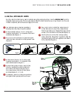
Page 21: ...re nut to connect the remaining wire on the first valve to one of the colored wires from the sprinkler wire Repeat this step until all valves in the manifold are connected Figure 3 Insert each wire nut into the corresponding cavity inside the Easy Wire organizer slide the mounting bracket onto the organizer and attach to the manifold Figure 4 At the timer remove 4 to 5 of the outer insulation and ...

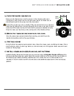
Page 22: ...ally test each sprinkler zone Check the valves pipes and fittings for leaks This is also the step in which you flush any debris i e dirt and rocks out of the system Make sure each head location is flowing freely 17 INSTALL HEADS AND NOZZLES AND ADJUST PATTERNS Install the heads fittings and nozzles one zone at a time using the and the following assembly pages as a guide Bleed Screw CHECK POLY MAIN...

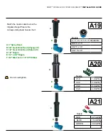
Page 23: ...B 3 4 Gear Drive Head Voyager II C 1 2 Gear Drive Head Saturn III D 1 2 Nipple E 1 2 x 3 4 Nipple F 3 4 Blu Lock x 1 2 FPT Elbow A B C D D E F F F Match the nozzle called out on the Irrigation Depot Plan to the corresponding head nozzle chart 4 6 8 10 12 15 Adjustable EST 5 x 15 SST 5 x 30 CST 5 x 30 Nozzle RED 0 75 GPM BLUE 1 50 GPM Nozzle GREEN 3 00 GPM ...

Page 24: ...ckwise Hold the base of the nozzle with your left hand With right hand gently turn nozzle top clockwise until it stops Rotate the ratcheting stem until the round dot highlighted here in red is lined up with the right edge of the desired spray pattern Hold the noz zle as shown in step 3 and gently turn the top counter clockwise until the round dot lines up with the left edge of the desired spray pa...

Page 25: ...rew counterclockwise until it is just clear of the nozzle Caution DO NOT turn the adjustment screw too far in either direction screw may come free of threads 6 The nozzle can then be removed by prying outward under the nozzle 7 Insert the correct replacement nozzle see tables 1 and 2 and align vertically then turn the screw back into place 8 Replace stem assembly into canister and screw cap on tig...

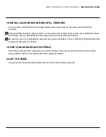
Page 26: ...ttings As your soil settles with time large rocks can cause premature failure Be careful not to cut or damage the sprinkler wires when backfilling It is very difficult to find and repair bad wiring after the system is buried 19 FINE TUNE NOZZLES AND PATTERNS After filling in the trenches manually turn on each sprinkler zone one at a time and fine tune the nozzle spray patterns Refer to the nozzle ...

Page 27: ...ively easy to work with and has a very long useful life We recommend Poly pipe for the constant pressure mainline part of your system the part going from your water source to your sprinkler valves However we recommend our environmentally friendly Blu Lock for all lateral sprinkler lines the pipes coming out of your valves that go to your sprinklers In a typical system lateral lines are over 80 of ...

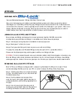
Page 28: ...tuitive your first time but with a little practice you will find that it makes a lot of sense Step 2 Wrap Place the front piece of the tape ribbon on the second thread from the end of the fitting or pipe and hold it with your finger Wrap the tape away from you and down and around the pipe at least two times and then start the third wrap with a 50 overlap of the previous wrap and so on until you re...

Page 29: ...is typically about 10 20 of the total pipe in your system Blu Lock is ideally suited for all sprinkler zone pipes those going out from the valve manifold because it is fast to install flexible has a very long useful life is clean to produce and is recyclable JOINING BLU LOCK PIPE AND FITTINGS Blu Lock pipe and fittings are designed to be used exclusively together NEVER use another manufacturer s p...

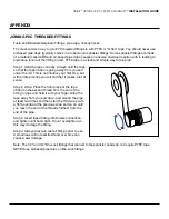
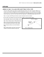
Page 30: ...d additional poly pipe APPENDIX JOINING 3 4 AND 1 BLU LOCK PIPE AND FITTINGS TO POLY PIPE 3 4 and 1 Blu Lock pipe have the same internal dimensions ID as 3 4 and 1 poly pipe However you should never use Blu Lock fittings with another manufacturers poly pipe In the event that your store does not carry 3 4 or 1 Blu Lock Pipe you may use standard poly insert barbs and clamps which are available at yo...

Page 31: ...Orbit Sprinkler System Designer Maps and parts list see www irrigationdepot ca ...

Reviews: