background image

P/N 20-07665-00 Rev 

L

           © Hydro Systems Company, Inc. 201

8

          HydroSystemsCo.com          Toll Free: 1.800.543.7184  1

Reference Manual 

LM-700 Series

Preface

This manual has been written and illustrated to present the basic 

installation, operation, and servicing instructions of the LM-700 Laundry 

Dispensing System. Guidelines will be suggested in reference to the 

preferred method of installation, however, the variety of equipment and 

the surrounding environment will dictate the actual installation of  

the LM-700.

MERCURY TL

 Laundry Dispensing System

Online and downloadable  

Product Manuals and Quick Start 

Guides are available at  

www.HydroSystemsCo.com 

Please check online for the latest 

version of this Reference Manual.

!

WARNING:

The LM-700 dispensing system 

is intended to be installed 

by experienced installers, in 

accordance with all applicable 

electrical and plumbing codes.

NOTE

: Always use proper 

lockout tagout procedures 

when installing and servicing 

dispensing systems. Please 

disconnect all washer and 

dispenser power sources any 

time the dispenser cabinet  

is open.

All machine and dispenser power 

must be disconnected during 

installation and/or any time the 

dispenser cabinet is opened.

Summary of Contents for Dover LM-700 Series

Page 1: ... LM 700 MERCURY TL Laundry Dispensing System Online and downloadable Product Manuals and Quick Start Guides are available at www HydroSystemsCo com Please check online for the latest version of this Reference Manual WARNING The LM 700 dispensing system is intended to be installed by experienced installers in accordance with all applicable electrical and plumbing codes NOTE Always use proper lockou...

Page 2: ...e 6 Prime Pumps when enabled 7 Password Access to Program Mode 7 5 Programming Introduction 8 Key Descriptions 8 Password Access to Program Mode 8 Prime Pump P 1 9 Clear Load Counter CLr 9 Operating Parameters oP 9 Lockout Period LP 9 Formula Program F 1 9 Pump Amount P1A 9 Delay Time D1A 9 Assign Pump A1A only in Occurrence Mode 9 Finish Program Fin 9 Filter Duration Fd 10 User Prime uPr 10 Passw...

Page 3: ...three physical pumps Pump Delay times programmed in minutes stagger the programmed pump doses throughout the wash load The Pump Lockout feature programmed in minutes prevents the machine operator from starting multiple doses in the same wash load If the load needs to be restarted the dispenser wash formula may be terminated early by pressing the Enter key for two seconds Loads are counted each tim...

Page 4: ... lower mounting screw holes Swing bracket out of the way drill lower holes and install lower wall anchors Screw bracket into place Lower unit onto wall mount bracket and press down until unit locks into place To remove unit from bracket depress lock button on the top of the bracket as you lift the unit from the mounting bracket Supply and Discharge Hoses We recommend use of 3 8 ID hose for supply ...

Page 5: ...ng machine has a single common for supply signals connect all the signal input common wires white with colored stripes to the machine s signal common wiring location In Automatic or Relay Mode trigger inputs match pump numbers i e trigger 1 pump 1 etc In Occurrence Mode connect wire pairs from each machine fill valve to two trigger inputs it does not matter which two of the three available trigger...

Page 6: ...n each pump runs based on pump assignments in the Assign Pump A1A screen in the programming menu Pumps 1 and 2 have two programmable amounts A and B which are treated in Occurrence Mode as separate pump programs Display indicates signal status pumps running and lockout status Auto Formula Select is always active but may be overridden by machine operator input Relay Mode requires no machine operato...

Page 7: ...n a lockout timer period If the dispenser is in a lockout timer period the display will indicate P 0 and the Scroll key will not select a pump number Password Access to Program Mode From the Formula Selection screen only press and hold the Enter Key for 2 seconds to access the Password input screen Press the Scroll Key to change the blinking digit to the desired value Press the Next Key to move th...

Page 8: ...ton Mode wash formula Press and hold 2 seconds to access Password input screen Starts and stops prime Performs actions as prompted in User Mode menu screens Program Mode Access all input screens from main menu loop screens selected with the Next key Performs actions in certain screens Input Screens Set the displayed value in all input screens selected with the Scroll key and exit back to main menu...

Page 9: ...his loop and Relay Mode is later selected all values will be retained for later use if Relay Mode is cancelled Use the Next key to step through all available menu screens in this loop Pump Amount P1A Every two seconds the screen alternates between the stored run time in seconds for the selected pump number and Pxx Press the Scroll key to select the desired pump number P1A P1B P2A P2B and P3 are th...

Page 10: ...ng Password Edit Pin Any three digit number may be input Press the Scroll Key to change the blinking digit to the desired value Press the Next Key to move the blinking digit Repeat for all digits and press the Enter Key when the desired password is present NOTE Note any password changes Access to Program Mode is not available if the password is lost Exit Program Mode End Press the Enter key to exi...

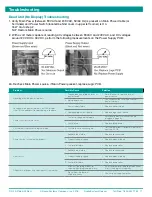
Page 11: ...n power terminals but LED display is not lit see additional troubleshooting info above 1 Power supply failure 1 Replace power supply 2 Damaged logic circuit board 2 Replace logic circuit board Pumps run slowly or not at all 1 Pumps not plugged in properly 1 Verify pump electrical connectors are plugged in properly 2 Pump failure 2 Replace failed pump Password will not access program mode 1 Passwor...

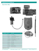
Page 12: ...r Supply 2 13 07725 00 Logic Circuit Board 3 13 06524 00 Pump Motor Detergent 2 Pin Plug 4 13 06398 06 Kit Pump Cover Teal 5 13 07028 368 Pump Tube Epdm w 3 8 Barb Ea 6 13 06396 00 Pump Spinner Assembly 13 07266 00 Power Cable 13 07267 00 Signal Cable 37 07087 02 Cabinet Front 37 07088 02 Cabinet Rear 13 07268 06 Power Switch Cover 13 07122 00 Mounting Bracket Kit Denotes items not shown ...

Page 13: ...t have a normal life shorter than one year or c failure in performance or damage caused by chemicals abrasive materials corrosion lightening improper voltage supply physical abuse mishandling or misapplication In the event the Products are altered or repaired by BUYER without SELLER S prior written approval all warranties will be void NO OTHER WARRANTY ORAL EXPRESS OR IMPLIED INCLUDING ANY WARRANT...

Page 14: ...ned See also Programming User Mode Operation O Occurrence Mode 3 5 6 9 10 Operating Modes 3 9 Operating Parameters oP 9 P Password access to program mode 7 8 10 edit Pin 10 Password Edit Pin 10 Power Failure 6 Prevent false activation of pumps 3 Prime Pump P 1 9 Product levels 3 Program Mode Screens 10 Programming 8 10 Pump delays 3 numbers 5 9 product levels A B 3 run time setting 6 9 Pump Amount...

Reviews: