background image

13 


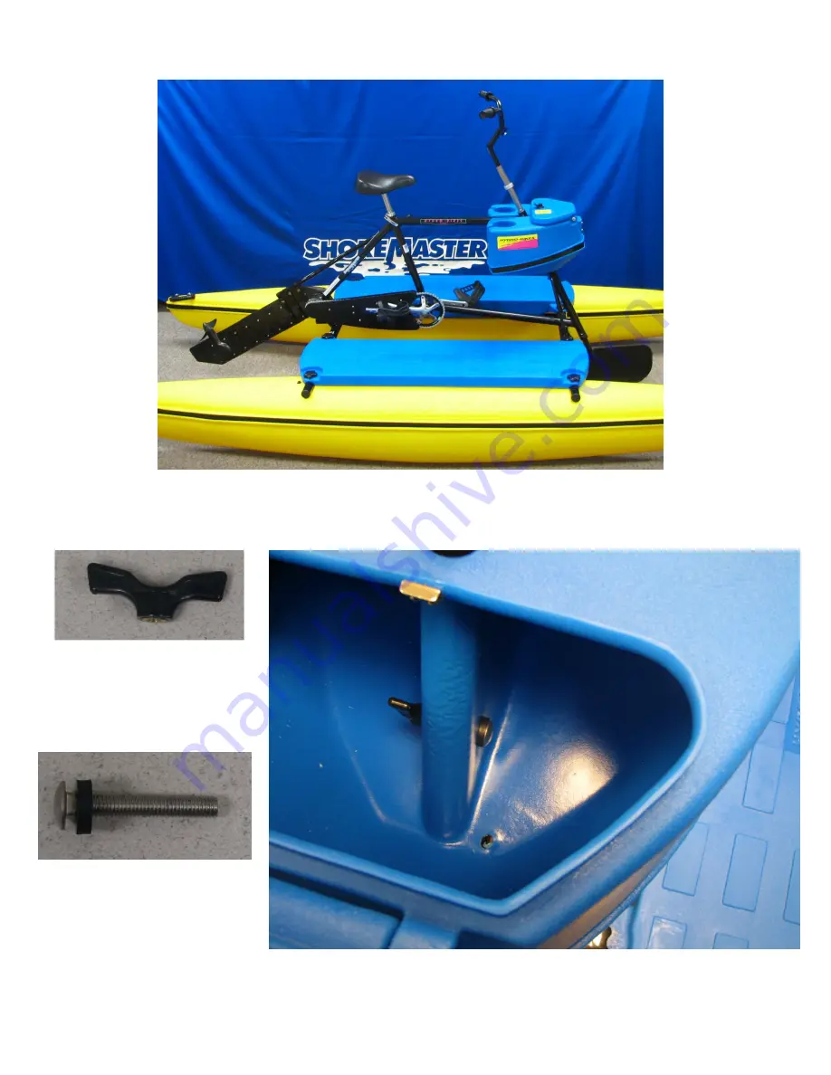
Set console on hydro-bike frame. 


Attach console to Hydro-bike frame using two carriage bolts, four rubber washers and two large wing 
nuts. Use rubber washers on both sides of console. 


Your EXPLORER

® 

is now ready for the water!!

Summary of Contents for Explorer

Page 1: ...t North Humboldt Iowa 50548 888 403 3012 www hydrobikes com European Representative Doceupoint Ltd The Old Methodist Chapel Great Hucklow Buxton Derbyshire SK17 8RG England Tel 44 1298 873800 Fax 44 1298 873801 Email enquiries doceupoint eu ...

Page 2: ...an upright traditional bicycle frame on a pair of 10 foot catamaran floats This pedal powered craft has an ultra efficient underwater propeller capable of pushing the craft beyond its hull speed of 6 7 mph to a sprint speed of 10 mph OWNER OPERATOR RESPONSIBILITY It is the owner operators responsibility to properly use and maintain this craft The instructions and warnings contained in this manual ...

Page 3: ...ble the EXPLORER Transport the EXPLORER Operate the EXPLORER Maintain the EXPLORER Then head for the lake river or ocean and you re ready to ride Safety Information Read this manual completely before assembling and operating your EXPLORER Consult a competent medical authority prior to undertaking any exercise or fitness program that involves the use of the EXPLORER ALWAYS wear a U S Coast Guard ap...

Page 4: ...lcohol or drugs Features The EXPLORER brings bicycling to the water Water cycling is fun safe and easy And like biking it s a wonderful way to have fun and get exercise Can be used for a wide variety of water activities Sightseeing adventure and exploration just like land biking Fishing Quietly pedal to the perfect spot Camping Takes you to where you want to go Photography The EXPLORER is stable a...

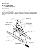
Page 5: ...e Computer designed drive system delivers over 90 theoretical efficiency Assembling the EXPLORER The frame including the drive train propeller pedals chain and chain guard comes pre assembled Some basic assemble however is required The procedure for this assembly is easy and takes only minutes ...

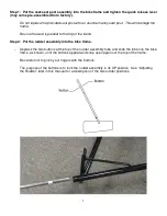
Page 6: ...op of the frame Step 2 Put the rudder assembly into the bike frame Depress the two buttons at the top of the rudder assembly tube and slide the tube into the bike frame as shown until the buttons appear and snap open again out the top of the frame Be careful not to pinch your fingers with the buttons The purpose of the buttons is to lock the rudder assembly in its UP position See Adjusting the Rud...

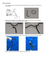
Page 7: ...ut do not tighten Assemble the handlebar into the handlebar stem Rotate the handlebar to your preference and tighten the nut with the provided 6mm Allen Wrench Place the stem into the rudder tube Be sure the handlebars are perpendicular to the rudder Again using the 6mm Allen Wrench tighten the handlebar stem ...

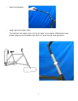
Page 8: ...he handgrips Lastly tighten the rudder collar The purpose of the rudder collar is to limit the depth of the rudder s DOWN position and provide support so the handlebar stem does not swell the tube when tightened ...

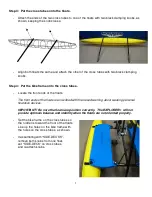
Page 9: ...oats The front ends of the floats are inscribed with the raised warning about wearing personal floatation devices IMPORTANT Be sure the floats are position correctly The EXPLORER will not provide optimum balance and stability when the floats are not oriented properly Set the bike frame on the cross tubes so the rudder is toward the front of the floats Line up the holes on the bike frame with the h...

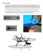
Page 10: ...Hand tighten only Do not use a wrench to tighten the black clamping knobs Hand tightening is all that is necessary Using a wrench or other tools may damage the knobs Note Four rubber washers are used there is one extra rubber washer and knob included Do not use a hammer or other tool to line up the holes of the bike frame and the cross tubes If the holes do not line up make sure you have followed ...

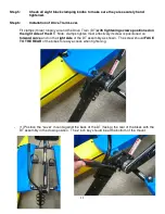
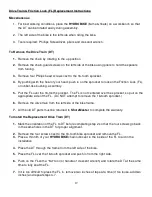
Page 11: ...d on the right side of the DT Note clamps tighten most effectively if screw is positioned on forward curve and on the right side of the DT assembly as shown The screw should FACE TO THE REAR of the bikes for easy access when tightening 1 Position the Lever mount against the back of the DT facing the rear of the bikes with the DT assembly in the down position The 2 inch key should be at the bottom ...

Page 12: ...clamp just above the BOTTOM of the mount and tighten securely making sure the key fits into the lever slot Tighten the top clamp securely The third clamp should be positioned between 1st and 2nd clamps Installation is now complete The lever should fit between the frame and the side deck when the Drive Train is in the up position 6 Recheck and re tighten clamps after first use and then periodically...

Page 13: ...ole on hydro bike frame Attach console to Hydro bike frame using two carriage bolts four rubber washers and two large wing nuts Use rubber washers on both sides of console Your EXPLORER is now ready for the water ...

Page 14: ...uck Set one fully assembled EXPLORER on a trailer or in a truck and fasten securely 2 On Top of a Car Set one fully assembled EXPLORER onto a car roof rack and fasten securely Make sure that the car roof rack is rated for the proper weight of the EXPLORER and other miscellaneous gear 3 Disassembled Disassemble the EXPLORER and transport the individual sections Two EXPLORERS can be transported in t...

Page 15: ... propeller drive train is in the DOWN position before you step onto the EXPLORER make sure the water is deep enough so that the drive train does not touch the bottom This may damage the propeller If possible choose a sandy shore when bringing the EXPLORER into land Do not ride up onto a concrete boat launch This may damage the floats Adjusting the Rudder Your EXPLORER has two rudder positions UP P...

Page 16: ... its frame saddle Step 7 Move the rudder to the DOWN position for the best steering results Step 8 Begin pedaling You can also pedal your EXPLORER in reverse Coming Back to Shore CAUTION If possible choose a soft or sandy shore If you come to a shore where there are rocks or concrete you may damage the EXPLORER When you are ready to go back to the shore and take your EXPLORER out of the water Step...

Page 17: ...ways to stop your EXPLORER 1 Stop pedaling 2 Pedal backwards 3 Turn the handlebars sharply to either the right or left so that the rudder is perpendicular to the floats To stop quickly pedal backwards and turn the handlebars sharply Reversing To travel backwards simply pedal in reverse The propeller drive train may come out of its frame saddle during abrupt reversing If this happens pedal forward ...

Page 18: ...tion of the friction lock will reduce the friction lock s ability to provide reverse thrust capability With repeated use or in rental situations lubricate the seat post with 1 2 drops of this lubricant Once a Year Winterize Change the drive train lubricant as described on page 24 ShoreMaster Products drive train lubricant P N 1000661 is the same USDA approved lubricant as above lubricant Failure t...

Page 19: ...ket so pull on the appropriate side of the FL Do NOT attempt to remove the 16 tooth sprocket 6 Remove the drive train from the left side of the bike frame 7 All the old DT parts must be returned to ShoreMaster to complete the warranty To Install the Replacement Drive Train DT 1 Mark the orientation of the FL to DT before completing step 2 so that the four screws go back in the same holes in the DT...

Page 20: ...uctions 1 9 of To Install the Replacement Drive Train DT Salt Water Environment Maintenance Chain Many resorts utilize two chains One is soaked in Diesel fuel and then replaces the chain on the bike They change chains every week Seat Before assembly of the bike take the spring off of the seat and spray with two coats of rust oleum primer and then spray it with one coat of black rust oleum paint Th...

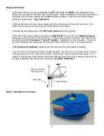
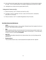
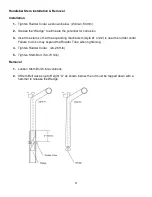
Page 21: ...ert the stem so that the expanding mechanism style 1 or 2 is near the rudder collar Failure to do so may expand the Rudder Tube when tightening 4 Tighten Rudder Collar 20 25 ft lb 5 Tighten Stem Bolt 50 70 ft lb Removal 1 Loosen Stem Bolt 5 6 revolutions 2 If Stem Bolt raises up to Height A as shown below then it must be tapped down with a hammer to release the Wedge ...

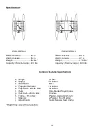
Page 22: ...ty Rider Cargo 600 lbs Common Features Specifications a Length 10 feet b Height 53 inches c Gear Ratio 8 6 1 d Propeller Diameter 12 inches e Prop Draft 200 lb rider 18 inches f Hulls Roto Molded Polyethylene g Hull Draft 200 lb rider 9 inches h Frame 19 inches Powder Coated Aluminum i j Steering Adjustments 2 Position Front Rudder Quick Release Seat Clamp Weight may vary with accessories ...

Page 23: ... the drain plugs and the rudder o rings and rotate the propeller drive train as shown Step 5 When the lubricant is fully drained rotate the propeller drive train to its DOWN position Step 6 Add new lubricant Step 7 Wet the o ring seals with lubricant and install Install and tighten stainless steel drain plug screws Be careful not to over tighten the drain plugs When the plug feels snug turn one qu...

Page 24: ...24 Parts Description EXPLORER I Hydrobike Console Bolt Bag Bottle of Oil ...

Reviews: