background image


The information contained herein is intended for the use of the individual(s) named above and those authorized to receive it.  Dissemination, distribution 
or copy of this information is strictly prohibited.


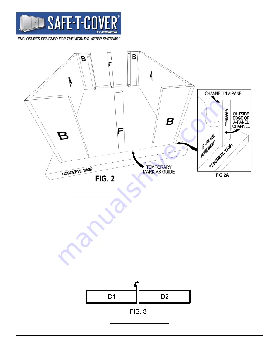
NOTE: model sizes and configurations vary, see the chart.  

3.


Inspect  the  alignment  of  the  “C”  (access)  panels  during  the  assembly  process.  Verify  that  their 
removal  and  replacement  allows  adequate  space  and  positioning  within  the  openings  and  with  the 
adjacent panels prior to attaching any bracket to the concrete. 

4.


Set the “C” (access) panels and the “F” (support) post in place with about a 3/16” gap on each side of 
the “C” panels as the roof is assembled.   

A.


Set the “D1” (roof) panel on a “B-A-B” (side-end-side) assembly.  Fasten the “D1” (roof) panel to the 
“B-A-B” (side-end-side) assembly through the holes provided (Fig 1) using two (2) hex headed screws. 

B.


Insert an Inside Roof Clip into the “D1” (roof) panel at the “B” panel studs (Fig. 1C).  Attach the clip to 
the “B” panel studs as shown using one (1) hex headed screw per clip. 

C.


Repeat step 4A and 4B for the “D2” (roof) panel and second “B-A-B” (side-end-side) assembly.   


Side View of Roof Panels 

Summary of Contents for Safe-T-Cover 800S Series

Page 1: ...TS Series 40 W x 174 L x 90 H 43 3 4 W x 177 L x 93 1 4 H 54 W x 188 L x 6 Thick 1 The concrete base should be 6 thick x 14 longer than enclosure ID x 14 wider than enclosure ID A Mark the concrete base for the outside of the enclosure 3 wider than ID and 3 longer than ID 2 The PVC masking film will help to protect the finish of the metal panels during installation These coatings should be left in...

Page 2: ...acent panels prior to attaching any bracket to the concrete 4 Set the C access panels and the F support post in place with about a 3 16 gap on each side of the C panels as the roof is assembled A Set the D1 roof panel on a B A B side end side assembly Fasten the D1 roof panel to the B A B side end side assembly through the holes provided Fig 1 using two 2 hex headed screws B Insert an Inside Roof ...

Page 3: ... per bracket Fasten the Inside Anchoring Brackets to the B panel studs and concrete along one side of the enclosure B Repeat Steps 6 and 6A on the other side of the enclosure 7 With the F support posts aligned within the spaces between the C panels Install an Inside Anchoring Bracket Fig 1B at the bottom of the F support posts A Attach the F support posts to the Inner Roof Connection Bracket tabs ...

Page 4: ...CONTENTS 1 Your assembly should include A 2 A end Panels B 4 B side Panels C 3 C access Panels D 1 Cw d access Panel E 1 D1 roof Panel F 1 D2 roof Panel G 2 F support Posts H 4 Outside Corner Anchoring Brackets 1 x 1 I 6 Inside Anchoring Brackets 3 x 3 J 4 Inside Roof Clips K 2 Roof Cover Plates L 1 Inner Roof Connection Bracket with Tabs M 1 Package of Anchors N 1 Package of Hex headed screws O 1...

Reviews: