Model 50386R Receiver
HydroLynx Systems, Inc.
A102682
Page 7
3.2 Radio: Tone and Squelch
The tone amplitude and squelch levels are factory set.
CAUTION: Adjustment should be made only by trained service personnel.
Tone amplitude is 800 mV
Squelch is set to 12db (SINAD measurement); Limit: <=0.5
•
V.
3.3 Input/Output
The 50386R receives Radio Frequency (RF) data transmissions from remote sites as
input. The receiver circuitry demodulates the Frequency Modulation (FM) signals into
audible tones. These tones, presented in ALERT Format, are 2133 Hz for logic "1" and
1920 Hz for a logic "0", and are the Frequency Shift Keying (FSK) output signal.
4.0 TESTING AND MAINTENANCE
4.1 Testing
4.1.1 RF Antenna Test
The antenna is tested for reflected power as if it were a transmitter antenna.
!
Attach a wattmeter and transmitter to the antenna cable.
!
Select the proper slug for reverse power and frequency testing (refer to wattmeter
manual).
!
Initiate a transmission. The duration of the transmission must be long enough to obtain
a stable reading on the wattmeter.
!
Compare the measured reading to the antenna system's rated reflected power.
4.1.2 Tone Out
!
Attach an oscilloscope to the tone out terminals.
!
Initiate a transmission to the receiver.
!
Verify that the signal is a 800 mVpp sine wave.
!
Refer to the radio manufacturer's service manual for adjustment instructions.
4.2 Radio Alignment
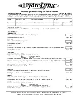
Refer to the Incoming Radio Inspection Form and to the radio manufacturer's service
manual.
CAUTION: Radio alignment should only be performed by trained service personnel.
Summary of Contents for 50386R
Page 4: ...HydroLynx Systems Inc Model 50386R Receiver Page 4 A102682...
Page 9: ......
Page 10: ......
Page 11: ......


