background image

Model 5052RD-K ALERT2 Receiver/Decoder 

HydroLynx Systems, Inc.


A102688 

Page 3


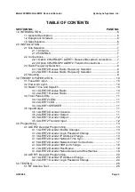
TABLE OF CONTENTS


SECTION NO. 

PAGE NO. 

1.0 INTRODUCTION ....................................................................................................... 6


1.1 General Description ........................................................................................ 6


1.2 Equipment Included ........................................................................................ 6


1.3 Specifications ................................................................................................. 6


2.0 INSTALLATION ......................................................................................................... 7


2.1 Site Selection .................................................................................................. 7


2.1.1 Antenna ............................................................................................ 7


2.1.2 5052RD-K ......................................................................................... 7


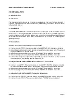
2.2 Connections .................................................................................................... 7


2.2.1 Option 5052RD-OP1 ALERT1 Receiver/Decoder Connections ........ 7


2.2.2 Option 5052RD-OP2 ALERT2 Transmit Connections....................... 7


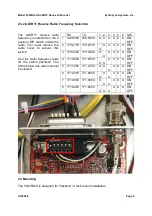
2.3 Radio Frequency Selection............................................................................. 8


2.3.1 ALERT2 Receive Radio Frequency Selection .................................. 8


2.3.2 ALERT1 Receive Radio Frequency Selection .................................. 9


2.3 Mounting ......................................................................................................... 9


3.0 THEORY OF OPERATION ..................................................................................... 10


3.1 Fused DC input ............................................................................................. 10


3.2 Power On Light ............................................................................................. 10


3.3 Radio: Tone and Squelch ............................................................................. 10


3.3.1 ALERT2 Receive Radio .................................................................. 10


3.3.2 ALERT1 Receive Radio .................................................................. 11


3.4 Front Panel LEDs ......................................................................................... 11


3.4.1 ALERT2 LEDs ................................................................................ 11


3.4.2 ALERT1 LED .................................................................................. 11


3.4.3 ALERT1 SPEAKER ........................................................................ 11


3.5 Input/Output .................................................................................................. 11


3.5.1 ALERT2 Decoder Console .............................................................. 11


3.5.2 ALERT2 Decoder Output ................................................................ 11


3.5.3 ALERT1 Decoder Output ................................................................ 12


3.5.4 ALERT2 Transmit Input .................................................................. 12


4.0 Programming ........................................................................................................... 13


4.1 ALERT2 Decoder Programming ................................................................... 13


4.1.1 ALERT2 Decoder Enable Changes ................................................ 13


4.1.2 ALERT2 Decoder Login Password Change .................................... 13


4.1.3 ALERT2 Decoder IP Address Change ............................................ 13


4.1.4 ALERT2 Decoder Network Time Sync ............................................ 16


4.1.5 ALERT2 Decoder Network Client Connections ............................... 17


4.1.6 ALERT2 Decoder SSH port change................................................ 18


4.1.7 ALERT2 Decoder Host Name ......................................................... 18


4.1.8 ALERT2 Decoder Name Servers and Host Names ........................ 19


4.2 ALERT1 Decoder Programming ................................................................... 20


4.2.1 ALERT1 Decoder IP Address Change ............................................ 20


4.2.2 ALERT1 Decoder Login Password Change .................................... 24


5.0 TESTING ................................................................................................................. 26


5.1 RF Antenna Test .......................................................................................... 26


Summary of Contents for 5052RD-K

Page 1: ...HydroLynx Systems Inc Model 5052RD K ALERT2 Receiver Decoder Instruction Manual Document No A102688 Document Revision Date February 2020...

Page 2: ...nsitive items If packing facilities are not available take the equipment to the nearest Post Office UPS or other freight service and obtain assistance with packaging Please write the RA on the outside...

Page 3: ...0 3 3 1 ALERT2 Receive Radio 10 3 3 2 ALERT1 Receive Radio 11 3 4 Front Panel LEDs 11 3 4 1 ALERT2 LEDs 11 3 4 2 ALERT1 LED 11 3 4 3 ALERT1 SPEAKER 11 3 5 Input Output 11 3 5 1 ALERT2 Decoder Console...

Page 4: ...ms Inc Model 5052RD K ALERT2 Receiver Decoder Page 4 A102688 5 2 Network Test 26 5 3 ALERT2 Data Out 27 5 4 ALERT2 Data Log 27 5 5 ALERT1 Data Out for OP1 ALERT1 Receiver Decoder Option 28 6 0 FORMS A...

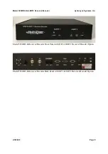
Page 5: ...Receiver Decoder HydroLynx Systems Inc A102688 Page 5 Model 5052RD K Receiver Decoder Front Panel with OP1 ALERT1 Receiver Decoder Option Model 5052RD K Receiver Decoder Back Panel with OP1 ALERT1 Re...

Page 6: ...adio with its own antenna connector The ALERT2 Encoder and transmit radio are mounted inside the 5052RD K Receiver Decoder desktop enclosure A GPS antenna and cable are included ALERT2 technology has...

Page 7: ...enna cable to the ALERT2 RX BNC female connector Attach the ground screw to earth ground using a 6 stranded copper wire The ground lug is provided on the ground screw Attach a computer network cable t...

Page 8: ...e the 5052RD K ALERT2 Receiver Decoder top cover to change radio frequencies 2 3 1 ALERT2 Receive Radio Frequency Selection The ALERT2 receive radio frequency is selected on the ALERT2 demodulator boa...

Page 9: ...ncy label for the switch positions The photo below has radio channel 2 selected 2 3 Mounting The 5052RD K is designed for desktop or rack mount installation RX TX 1 2 3 4 5 6 SW 1 169 5000 169 5000 X...

Page 10: ...on when power is connected The power input fuse is mounted on the back panel The Model 5052RD OP1 ALERT1 Receiver Decoder Option receives ALERT1 audio signals from the ALERT1 receive radio and decode...

Page 11: ...toggle switch is in the down position towards the word SPEAKER when the Model 5052RD OP1 ALERT1 Receiver Decoder Option is installed 3 5 Input Output 3 5 1 ALERT2 Decoder Console The ALERT2 decoder ca...

Page 12: ...ke TCP IP network connections with remote base station computer IP addresses and ports The ALERT2 Receiver Decoder will attempt a reconnect every 30 seconds 3 5 3 ALERT1 Decoder Output ALERT1 decoder...

Page 13: ...in as root allow changes to be made by making the root file system read write with the command mount o remount rw The file system can now be changed by adding deleting and editing files The read write...

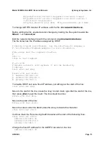
Page 14: ...ection the IP address follows inet addr and the Physical address follows HWaddr For example ifconfig Enter eth0 Link encap Ethernet HWaddr 00 d0 69 4c f7 db inet addr 192 168 1 92 Bcast 192 168 1 255...

Page 15: ...e loopback interface auto lo iface lo inet loopback auto eth0 disable automatic eth0 up down it will be handled by ifplugd iface eth0 inet dhcp iface eth0 inet static address 192 168 1 92 netmask 255...

Page 16: ...e current to the nearest second ALERT2 data packets received from the radio are time stamped with the current ALERT2 decoder time when deciding is finished The base station software uses the ALERT2 de...

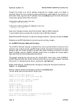
Page 17: ...o quit the insert server 192 168 1 24 prefer In the example above the time server IP address is 192 168 1 24 Save your changes and quit type the command wq no Enter required To quit without saving use...

Page 18: ...anged to allow firewall routing To change the ssh port edit the file etc ssh sshd_config Before editing the file enable decoder changes by making the file system read write mount o remount rw Edit the...

Page 19: ...again 4 1 8 ALERT2 Decoder Name Servers and Host Names The ALERT2 Decoder defines its name servers in the file etc resolv conf Display the current name servers with the command cat etc resolv conf En...

Page 20: ...il done then press Esc to quit the insert For example Local alert2 decoder name change as needed 192 168 1 92 a2decoder1 NovaStar5 servers 192 168 1 98 novastar5a 192 168 1 99 novastar5b Esc Save your...

Page 21: ...2RD OP1 ALERT1 Serial to IP line and Serial Number MAC column For example the IP address 192 168 1 148 is assigned the Physical Address 00 40 9d a2 ae 77 Use a Windows internet browser to connect to t...

Page 22: ...Systems Inc Model 5052RD K ALERT2 Receiver Decoder Page 22 A102688 Click the Configuration Network link on the left side of the page to display network configuration The current network configuration...

Page 23: ...eiver Decoder HydroLynx Systems Inc A102688 Page 23 Click the selection to Use the following IP address Enter the fixed IP Address Subnet Mask and Default Gateway Click Apply For example change the IP...

Page 24: ...en wait for the browser to reconnect 4 2 2 ALERT1 Decoder Login Password Change Use a Windows internet browser to connect to the ALERT1 Decoder by typing the IP address on the browser address line Ent...

Page 25: ...Receiver Decoder HydroLynx Systems Inc A102688 Page 25 Click the Configuration Security link on the left side of the page to display network configuration Enter the new login password on this page co...

Page 26: ...e IP address following the label inet addr ifconfig Enter eth0 Link encap Ethernet HWaddr 00 d0 69 4c f7 db inet addr 192 168 1 92 Bcast 192 168 1 255 Mask 255 255 255 0 If the IP address is not corre...

Page 27: ...II format strings starting with P and N are displayed 5 4 ALERT2 Data Log The ALERT2 Decoder ASCII output is written to log files on the SD card Connect to the ALERT2 Decoder CONSOLE through the netwo...

Page 28: ...UTC The second line starting with N is the MANT packet extracted from the Airlink P line above The packet receive time is in fields 2 to 7 as YYYY MM DD hh mm ss ssssss in UTC The ALERT2 station addre...

Page 29: ...ynx Systems Inc A102688 Page 29 6 0 FORMS AND DRAWINGS WD100624 5052RD K Test Results VS108642 5052RD K Chassis Block Wiring Diagram VS108643 5052RD K Harness Power Wiring Diagram VS108711 5052RD K Re...

Page 30: ...C Gqrqs tqGu HqrvHqGC rwqrJC xa 4 U fg h3i2 3y k fg h3i2 93 g h4 k fg h3i2 3y g h4 k fg h3i2 4 U b X d k x R X U Y T Z x R X U fg h3i2 4 U V U z X k 4 Y k id S Z X j X bR W T U g d T g d Z U T m Y d...

Page 31: ...0 1 2 3 4 62 7 862 3 862 7 0 9 2 3 0 1 5 2 4 2 3 2 4 0 1 2 3 4 0 1 2 3 4 0 1 2 3 45 0 1 2 3 45 3 0 1 2 3 4 3 0 1 2 3 45 5 2 67 3 2 6 1 6 0 1 52 67 4 0 1 2 3 2 0 32 2 52 67 4 0 1 2 3 2 0 32 2 0 0 7 52...

Page 32: ...8 5 7 76 1 8 3 1 5 4 5 67 3 78 2 4 2 6 2 1 4 4 1 278 5 46 4 5 67 5 2 3 5 7 5 75 8 2 5 2 1 2 1 5 9 3 0 8 2 28 65 6 5 5 8 3 677 3 4 9 5 5 67 2 2 4 6 3 6 5 1 5 8 4 1 5 3 677 3 4 618 5 5 6 7 61 3 677 3 4...

Page 33: ...64 4 4 4 4 6 4 38 4 9 3 9 7 4 4 9 3 9 7 4 7 444 3 2 3 2 0 7 0 7 444 3 2 3 2 0 7 0 3 4 0 1 0 1 0 1 0 1 4 0 1 0 1 9 3 5 3 4 0 1 0 1 0 1 0 1 4 0 1 0 1 3 4 0 1 0 1 9 3 5 3 4 0 1 0 1 9 3 0 1 0 1 9 3 0 1 0...

Reviews: