Model 5052RD-K ALERT2 Receiver/Decoder
HydroLynx Systems, Inc.
A102688
Page 7
2.0 INSTALLATION
2.1 Site Selection
2.1.1 Antenna
The receiver antenna should be installed at an elevation that is as high as practical. If
possible, install the antenna onto a radio tower, tall building, or other tall structure. Refer
to Radio Path Survey.
2.1.2 5052RD-K
The 5052RD-K ALERT2 Receiver/Decoder enclosure should be located near the antenna
tower to reduce the length of the RF transmission line and the associated RF signal loss.
It is recommended that a lightning arrestor with ground lug (optional) be placed between
the ALERT2 receiver back panel BNC connector and the antenna to protect against
lightning damage.
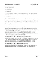
2.2 Connections
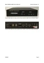
All wiring connections are located on the back panel.
!
Connect the ALERT2 RX antenna cable to the ALERT2 RX BNC female connector.
!
Attach the ground screw to earth ground using a #6 stranded copper wire. The ground
lug is provided on the ground screw.
!
Attach a computer network cable to the ETHERNET RJ45 ALERT2 connector.
!
Attach a computer serial cable to the SERIAL DB9 female ALERT2 connector.
!
Connect the AC power supply to the 3-pin 12VDC connector. For best results, connect
the power supply to a battery backed system (UPS).
2.2.1 Option 5052RD-OP1 ALERT1 Receiver/Decoder Connections
!
Connect the ALERT1 RX antenna cable to the ALERT1 RX BNC female connector.
An external antenna cable splitter can be used to share the same receive antenna.
!
Attach a computer network cable to the ETHERNET RJ45 ALERT1 connector.
!
Attach a computer serial cable to the SERIAL DB9 female ALERT1 connector.
2.2.2 Option 5052RD-OP2 ALERT2 Transmit Connections
!
Connect the ALERT2 TX antenna cable to the ALERT2 TX BNC female connector.
!
Connect the ALERT2 GPS antenna cable to the GPS SMA female connector.

