background image


                                                                                                                                                Page 36

»

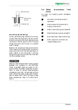
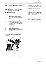
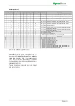
Clean both strainer.

»

Check the base and its connections 
for limescale deposits and clean if 
necessary.

»

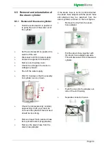
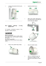
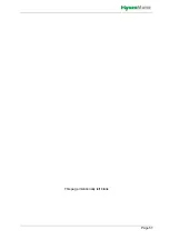
Insert a new O-ring in the base.

»

Insert new O-rings between the cyl-
inder halves and in the steam hose 
adapter.

»

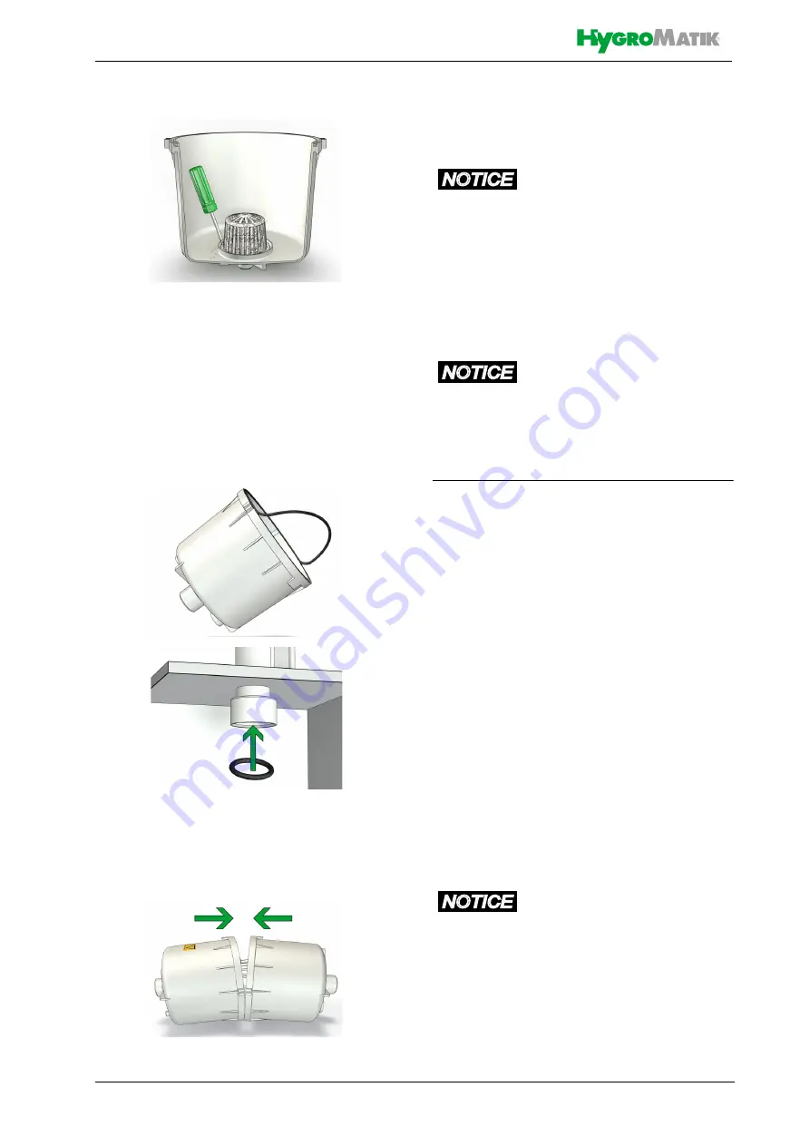
Put the cylinder halves together and 
reconnect them with the flange 
clamps.

»

When assembling the cylinder, make 
sure that the brackets and reinforce-
ments are on top of each other.

Risk of functional disruption!

Use descaler or cleaning detergents only for
cylinder and heater element cleaning. Do not
introduce in cylinder base or apply to hoses!

Prior to restarting the unit, make sure that the
device assemblies in question are thoroughly
flushed or rinsed.

Possible damage to the unit!

Excessive use of force during mechanical
cleaning of the cylinder or heating element
can damage these parts of the unit.

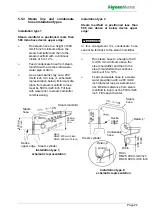
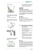
9.5.3 Cleaning the connecting hoses,

base connections, fine filter

and drain pump

»

Check the connection hoses for con-
dition and free passage.

»

Check all connections of the cylinder 
base for free passage.

»

Clean the hoses and connections if 
necessary.

»

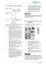
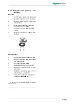
Remove the fine filter on the water 
connection side from the solenoid 
valve and clean it under running 
water.

»

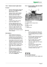
Clean the drain pump as described 
in the section of the same name.

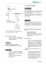
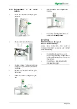
When operating with partially softened water
or tap water, scale may be discharged with
the steam flow and may settle in the nozzle
positioned in steam hose adapter. Therefore,
this nozzle should be inspected regularly as
part of the general maintenance review and
cleaned if necessary.

NOTICE

NOTICE

NOTICE

Summary of Contents for FlexLine FLH03

Page 1: ...FlexLine Electric Heater Steam Humidifiers ÁFLH ENKÈ FLH EN E 8881164 Manual ...

Page 2: ...anual can be found at www hygromatik co uk HygroMatik GmbH grants the legal user of this product or device the right to use the Work s solely within the scope of the legitimate operation of the product or device No other right is granted under this licence In particular and without prejudice to the generality of the foregoing the Work s may not be used sold licensed transferred copied or reproduce...

Page 3: ... Output Setting 11 4 4 Mechanical Construction 11 5 Mechanical installation 12 5 1 Environment Parameters to be met and Mounting Recommendations 12 5 1 1 Dimensions and Mounting Directions 13 5 2 Unit Installation Check 15 5 3 Absorption Distance BN 16 5 3 1 Determining the Absorption Distance 16 5 3 2 Absorption Distance Nomogram 17 5 4 Steam Manifold 18 5 4 1 General installation guidelines 18 5...

Page 4: ...eaning O ring replacement 35 9 5 3 Cleaning the connecting hoses base connections fine filter and drain pump 36 9 5 4 Level control device cleaning 37 9 5 5 Cleaning the vent hole on the pipe elbow 37 9 5 6 Reinstallation of the steam cylinder 38 9 6 Removal and installation of unit components 39 9 6 1 Blow down pump removal cleaning reinstallation 39 9 6 2 Solenoid valve removal reinstallation 40...

Page 5: ... for the operation of the unit This is not applicable to StandardLine devices here the documentation of the controller is included in the operation manual Retention Please retain these operating instructions in a secure always accessible location If the product is resold turn the documentation over to the new operator If the documenta tion is lost please contact HygroMatik Versions in Other Langua...

Page 6: ...el may operate the unit Persons transporting or working on the unit must have read and understood the cor responding parts of the Operation and Main tenance Instructions and especially the chapter 2 Safety Notes Additionally operating personnel must be informed of any possible dangers by the pro vider A copy of this manual is to be placed at the unit s operational location By construction HygroMat...

Page 7: ...sult from it Cleaning and user maintenance of the unit must not be undertaken by children without supervision 2 1 3 Unit Operation Risk of scalding Uncontrolled hot steam escape in case of leaking or defective components possible Switch off unit immediately For Ministeam devices applies Risk of scalding No persons may be under the cloud of steam blowing out at a distance of approx 1 m 40 inch in t...

Page 8: ...s electrical voltage Any work on the electrical system to be per formed by certified expert staff electricians or expert personnel with comparable training only Steam operation may only be started when the unit cover is closed During maintenance or installation work the device must be disconnected from the power supply and secured against being switched on again The absence of voltage must be ensu...

Page 9: ...oods Upon receipt of the unit confirm that model and serial number on the name plate match those specified in the order and delivery documents the equipment is complete and all parts are in perfect condition In case of damage from shipment and or missing parts immediately notify the carrier or supplier in writing Time limits for filing freight claims with ship ping companies are Time limits for so...

Page 10: ...ineral free and germ free When fully desalinated water is used the cy linder water is almost totally clear of minerals This situation guarantees a long lifetime of the cylinder s and the heater element s since virtually no hardeners will fall out and no min eral deposits will occur Such the number of inspections and or maintenance operations required will be reduced to a minimum When tap water is ...

Page 11: ...e open area below the heater element s and are removed through periodic maintenance The blow down pump itself has wide openings and can flush out smaller pieces of mineral deposit This extends the service life of the unit and reduces the required maintenance interval On blow down water flows from the pump into the drain hose system For maintainence purposes the cylinder water may be pumped out by ...

Page 12: ...frost may damage the steam cylinder the solenoid valve and pump as well as make hoses burst Relative humidity must not exceed 80 r h since values beyond may lead to electronic malfunction or dam age Installation in a closed room requires aeration and eventually temperature conditioning in order to meet the a m environmental conditions The steam humidifier should be installed as close as possible t...

Page 13: ...1170 46 785 30 9 420 16 5 1000 39 4 660 25 6 Detailed measurements under https www hygromatik com files pdf hygromatik flexline dimensionsv13 pdf 3D models under https www hygromatik com en downloads Units with production date January 2022 and earlier X 540 A 390 Wall clearances When mounting the steam humidifier the wall clearanc es shown in the fig below must be obeyed distance to designated pat...

Page 14: ... the mounted screws hook in the unit and ensure safe suspension mark the holes for the lower suspen sion brackets screws remove the unit drill holes and dowel hook in the unit and mount the lower screws firmly To function properly the steam humidi fier must hang level and plumb When choosing the installation loca tion consider the necessary distance between the unit and existing desig nated paths ...

Page 15: ... Steam hose installed with a 5 10 minimum incline decline see chap ter Steam line Condensate hose features a loop functioning as a steam barrier see chapter Condensate hose Steam manifold s properly positio ned All bolts and clamps properly tighte ned Steam manifold s horizontally mon ted and suspended on the free end if required All seals o rings in place All ventilation slots on housing top unob...

Page 16: ...humidification t2 in C with steam humidifiers the change in air temperature due to humidification may be disregarded t1 or t2 Specific increase in humidity x in g kg can be determined in the h x diagram quantity of steam introduced in kg h air speed wL in m s in air duct Total length lD of the steam manifold installed in the air duct Length ID of the usable steam manifold depends on the dimensions...

Page 17: ...Page 17 5 3 2 Absorption Distance Nomogram Source Henne Erich Luftbefeuchtung Air Humidification 3rd Edition 1984 Page 101 Olden bourg Industrieverlag Munich ...

Page 18: ...d depending on the overall pres sure situation These modifications must be coordinated with your expert dealer Water drain We point out that according to the Ger man Association of engineers VDI guideline VDI 6022 a water drain must be provided within the absorption distance inside the air duct When increased airflow speed is encoun tered Air flow rates beyond 3m s 9 84 ft s may lead to condensate...

Page 19: ...y staggered with respect to air flow direction in case of Lmin s above not to be met very flat by tilting the steam manifold 30 45 towards the air flow direction the mini mum upper clearance can be reduced to 70 mm 2 8 inch Min mm inch H1 H2 30 45 DN25 1 182 7 2 168 6 6 225 8 6 DN40 1 1 2 193 7 6 179 7 2 230 9 1 narrow high identical lenghts one on top of the other staggered laterally if possible ...

Page 20: ...o possible Standard manifold dimensions mm inch Special lengths on demand Number and size of the steam manifolds available as well as the nominal diameter of the repective steam and condensate hoses may be taken from the tables shown in chapter Technical Data 220 8 7 400 15 7 600 23 6 900 35 4 1200 47 2 1450 57 1 Steam manifold arrangement Steam supply Air flow direction ...

Page 21: ...m hose installation Pressure conditions within the duct are influenced by device steam output steam line layout and the duct composition itself In some rare situations it may become necessary to optimize steam line layout for achieving the results intended Respect minimum bending radii DN 25 Steam hose Rmin 200 mm 8 DN 40 Steam hose Rmin 400 mm 16 5 5 2 Condensate hose layout only for electrode st...

Page 22: ...r below device upper edge In this arrangement the condensate hose cannot be fed back to the steam humidifier Run steam hose to a height of 400 mm 16 mm minimum above the steam humidifier and then to the steam manifold with a continuos decline of 5 to 10 Feed condensate hose to a waste water pipe drain with a 200 mm 8 inch diameter loop as a steam bar rier Minimum distance from steam manifold to lo...

Page 23: ...is located in the water supply line It prevents in accordance with DIN EN 61770 the backflow of water Supply water must not exceed 40 C 104 F Allowable range of water pressure 1 to 10 bar 14 5 to 145 psi 100 x 103 to 100 x 104 Pa For connection to the water supply pipe make use of a water hose Blow down water must drain freely The following applies to electrode steam humidifiers Use feed water wit...

Page 24: ...th softened water at operating tempera ture conductivity level usually is higher than is the case with tap water If using a water softening system we recommend diluting the softened water with normal tap water to produce an overall hardness between 4 8 gH This value can be set lower if the water does not foam 6 2 Water supply Foreign material in water supply pipe may cause premature wear of the so...

Page 25: ... be on the same pressure level In case of a drain connection on posi tive pressure pls consult your expert dealer Guidelines for water discharge composi tion Use flexible water hose Do not buckle drain hose Discharge line and drain pipe material must be temperature resistant up to 95 C 203 F How to proceed Run a 1 1 4 drain hose of 250 to 1000 mm 10 to 40 inch length into a pressure free outlet ac...

Page 26: ...ter cooling system HyCool not available for FLP XX TPRO units HygroMatik offers an option for limi ting the steam humidifier wastewater temper ature in order to protect thermosensitive wastewater pipe lines By blending with tap water during blow down wastewater temper ature is below 60 C 140 F as long as inlet water temperature does not exceed 30 C 86 F 6 4 Water connections final check Go down th...

Page 27: ...o commencing electrical installation work steps must be taken to guard the sen sitive electronical components of the unit con trol against damage from electrostatical discharge 7 1 Electrical installation approach Provide fuses with a contact gap of at least 3mm per pole Install a separate main connection for each steam cylinder including main circuit breaker main switch etc Make main connection a...

Page 28: ...ays pressure controllers air interlock devices etc in series across ter minal 1 and 2 Contacts across terminals 1 and 2 must be potential free and properly rated Rating must comply with the control voltage in use Best practice implies the integration of a max hygrostat in the safety interlock wiring to pro tect against over humidification due to a r h sensor malfunction Model M25 M25 with MSI M32 ...

Page 29: ... across terminals 1 and 2 Supply voltage in accordance with name plate voltage rating All ectrical connections made accor ding to the wiring diagram Is the sensor temperature sensor or r h sensor depending on the appli cation scenario properly connected to the main p c b make sure that the input selected is adequate for the type of sensor installed with respect to the signal type and range specifi...

Page 30: ...and then commences normal operation During self test the On Off button icon flashes for a couple of seconds On completion of the test the software version is displayed for a short moment Consequently normal opera tion is commenced However steam is not produced without a demand pen ding Step 4 Trigger steam demand Set control for commissioning check for permanent steam demand and close safety inter...

Page 31: ...ntrols manuals Following hereafter pls find 2 service messages denoted as examples Steam_amount_counter is output when the pre set produced steam amount is reached Maintenance of the device is necessary Cycles_main_contactor x is indicated when the number of cycles pre set for main contactor x x 1 5 is reached The main contactor should then be replaced and the counter reset s Service submenu in th...

Page 32: ...aintenance work is commenced After that wait approx 10 mins before starting maintenance work Check steam cylinder temperature by cau tious approximation with hand do not touch Risk of scalding Water pumped or drained from the steam cylinder may have a temperature of up to 95 C 203 F Wear proper PPE Personal Protection Equipment Take care of ESD protection The electronic components of the humidifie...

Page 33: ... built up Water quality When tap water is used it must be taken into account that cleaning intervals shorten as the carbonate hardness level increases As a general rule it is preferable to operate the unit with fully demineralized water since ope ration will not be affected by mineral deposits and flushing loss will be minimized Possibly maintenance intervals may be extended by moderately increasi...

Page 34: ... cool down Check the temperature by carefully approaching it with your hand do not touch the cylinder if the rest heat should be too strong Remove Super Flush solenoid hose from cylinder bottom if applicable Remove the steam hose from the steam hose adapter If the steam hose is not to be disconnected the steam hose adapter with the steam hose still attached may be detached from the steam cylinder ...

Page 35: ...inder halves have sharp edges and can jump off during dismantling Eye injuries are possible Wear proper PPE Personal Protection Equip ment Remove the cylinder flange clamps Separate cylinder halves Remove the used O rings between the cylinder halves in the base and in the steam hose adapter Clean the cylinder inside Clean the heating element s by scraping or scrubbing A small amount of scale harde...

Page 36: ... Possible damage to the unit Excessive use of force during mechanical cleaning of the cylinder or heating element can damage these parts of the unit 9 5 3 Cleaning the connecting hoses base connections fine filter and drain pump Check the connection hoses for con dition and free passage Check all connections of the cylinder base for free passage Clean the hoses and connections if necessary Remove ...

Page 37: ...er housing and loosely affix to unit rear wall with the 2 screws Insert the 2 screws remaining into the open level control device enclo sure mounting holes while position ing the ground wire connection eyelet under the lower left screw Handtighten all of the screws A functional check of the level control device may only be accomplished while the device is installed into the unit 9 5 5 Cleaning the...

Page 38: ...m hose adapter to cylin der Affix the steam hose adapter with the clip Follow the handling instructions in the section Leakage test Risk of functional disruption Risk of material damage Loose cable connections may result in increased transition resistance and contact area overheating Check all cabling terminals and plugs for tight seating Plugs must sit on their respective contacts as far as they ...

Page 39: ...yonet lock Remove residues from pump and drain hoses Remove the used o Ring 33 the figures refer to the illustration on the next page Reinstallation Moisten the new O ring 33 and insert into cylinder base 37 hori zontal stub Push pump back into cylinder base and bolt to bottom plate encorporat ing the vibration buffer 42 and washers saved during removal Moisten O ring 31 and insert into adapter Sl...

Page 40: ...lve mounting screws Remove solenoid valve from hous ing bore Reinstallation Reinsert fine filter into solenoid valve Reinsert solenoid valve with seal in unit housing bore Bolt down solenoid valve Reestablish tap water connection Reconnect electrical cable to sole nod valve Reattach connecting hose 20 to cylinder base using clamp Follow the handling instructions in the section Leakage test the num...

Page 41: ... into the terminals of the wiring connector fol lowing the markings made when dis sembling Polarity is not an issue Refit thermo switch capillary tube to heater element s using retainer clips Reassemble steam cylinder and reinstall in humidifier housing as described in the Reinstallation of the steam cylinder section Follow the handling instructions in the section Leakage test 9 6 4 Thermo switch ...

Page 42: ...e too high the main con tactor K1 drops while the electronic control enters fault state 120 i e Thermoswitch In case of one of the thermo switches trig gering repeatedly the reason for this must be identified prior to further unit usage Thermo switch es on steam cylinder cover After the unit has cooled down the thermo switch that has triggered may be identified by passage measurement as long as it...

Page 43: ... O rings seals after 15 30 minutes of operation In case of leakage turn off power supply and secure against being switched on again Find leakage and eliminate Check again Follow the instructions in the section funktional check 9 8 Functional check Run the system with maximum out put for a couple of minutes Check hose connections and seals for leakage 9 9 Finishing maintenance Reattach unit housing...

Page 44: ...e humidifier is made up of metal parts and plastic parts In reference to European Union directive 2012 19 EU issued on 4 July 2012 and the related national legislation please note that The components of the electrical and elec tronic devices must not be disposed of as municipal waste and therefore the method of waste separation must be applied The public or private waste collection systems defined...

Page 45: ...Page 45 11 Declaration of Conformity ...

Page 46: ...CY45 380 415V compl incl O ringset Steam cylinder without SuperFlush nozzle 16 1 SP 03 01056 Steam cylinder FLH06 CY08 380 415V compl incl O ringset 16 1 SP 03 01085 Steam cylinder FLH09 CY08 380 415V compl incl O ringset 16 1 SP 04 01026 Steam cylinder FLH15 CY17 380 415V compl incl O ringset 16 1 SP 04 01055 Steam cylinder FLH25 CY17 380 415V compl incl O ringset 16 1 SP 06 01086 Steam cylinder ...

Page 47: ...cable short 27 2 2 CN 07 01012 Water level sensor complete with cable long 1 1 1 1 E 2209018 Adapter for Steam hose for cylinder CY08 DN40 25 1 1 1 2 2 2 4 4 E 2209008 Adapter for Steam hose for cylinder CY17 45 DN40 40 2 1 1 1 1 1 2 2 2 4 4 E 2209002 Clip for adapter Water feed 25 1 1 1 WF 03 00012 Solenoid valve FLH03 09 208 240V 0 2 10bar with mounting set 25 1 1 WF 04 00012 Solenoid valve FLH1...

Page 48: ...r comparment plug socket 1 1 1 1 1 1 1 1 1 1 CN 07 00020 Mainboard fuse 2 5A 1 1 1 1 1 1 1 1 CN 07 00025 Mainboard fuse 0 5A used when power supply for the mainboard is generated by a transformer 1 1 CN 07 00028 Mainboard fuse 1 0A used when power supply for the mainboard is generated by a transformer 1 1 CN 07 00030 Extension board double cylinder FlexLine 1 1 1 1 1 1 1 1 1 1 CN 07 00040 Relay bo...

Page 49: ...Page 49 This page intentionally left blank ...

Page 50: ...Page 50 This page intentionally left blank ...

Page 51: ...Page 51 This page intentionally left blank ...

Page 52: ... 9 80 0 87 0 91 0 100 0 108 5 Electrical connection 1 Rated power kW 20 6 22 8 24 5 27 3 30 3 32 6 34 1 37 8 40 7 2 x 27 3 30 3 32 6 2 x 34 1 37 8 40 7 Nominal current A 31 2 32 9 34 1 41 5 43 7 45 4 51 8 54 6 56 6 2 x 41 5 43 7 45 4 2 x 51 8 54 6 56 6 Fuse A 3 x 35 3 x 50 3 x 63 2 x 3 x 50 2 x 3 x 63 Terminals max mm 10 Number of steam cylinder Control Separate control voltage 3 Steam hose connec...

Page 53: ...Electrical connection 1 Rated power kW 20 6 22 8 24 5 27 3 30 3 32 6 34 1 37 8 40 7 2 x 27 3 30 3 32 6 2 x 34 1 37 8 40 7 Nominal current A 31 2 32 9 34 1 41 5 43 7 45 4 51 8 54 6 56 6 2 x 41 5 43 7 45 4 2 x 51 8 54 6 56 6 Fuse A 3 x 35 3 x 50 3 x 63 2 x 3 x 50 2 x 3 x 63 Terminals max mm 10 Number of steam cylinder Control Separate control voltage 3 Steam hose connection mm 1 x 40 6 Water consump...

Page 54: ...e FLH model composition The number of cyl inders and heater elements vary with respect to the complete FLH series The index numbers in the figure corre spond to the spare parts list 30 31 32 33 42 6 14 15 34 25 27 19 35 37 18 17 16 4 5 1 2 3 22 21 23 24 7 ...

Page 55: ...Page 55 15 View of housing FLH03 FLH25 FLH40 FLH50 FLH30 FLH80 FLH100 70 56 57 70 56 57 56 57 70 70 56 57 56 57 ...

Page 56: ...Ein Unternehmen der Gruppe 100 Lise Meitner Str 3 D 24558 Henstedt Ulzburg Phone 49 0 4193 895 0 Fax 33 eMail hy hygromatik de www hygromatik com member of CAREL Group ...

Reviews: