background image

28  


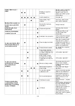
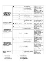
limits 1000 < mA < 
2500 

●  ●   


Blockage in system 
plumbing 

Bypass system (plumbing) 
by close-looping pump 
heads (in-out), turn on 
pump and confirm system 
current draw 

●  ●  ●  ●  ●   

Leak in plumbing 

Find leak, fix 


  ●   


Seized pump head 
(debris) 

close-loop pump heads 
and confirm operation 

Module life counter on 
board runs out (>720 
days) 

  ●   


Module life has been 
exceeded 

Change module 

program gets lost, 
hits a trap 


  ● 

Programming errors 

watchdog timer resets 
system 

Internal pre-filtration 
counter runs out 


  ● 

Change pre-filter, reset 
counter values (See 
commands) 

In process mode, after 
20 seconds if there is 
no module current 


  ● 

Electrode not connected 

Verify connection between 
stack and power supply 

  ●   


  ● 

Power supply saturated 

Disconnect module leads, 
manually turn on power.  
Voltage should be read.  If 
there is no voltage, restart 
system and repeat test. 


  ● 

Polarity failed to switch       

Re-connection or replace 
new PCBA 


  ●   


Pump failed, module 
current will plummet to 0 
as dilute compartment is 
fully de-ionized 

Verify pump operation* 

In process mode, 
when the cut is below 
the control level 
(statics) 


  ●   


Pump failed, cut will 
plummet to 0 as dilute 
compartment is fully de-
ionized 

Verify pump operation* 

  ●   


  ● 

Module is badly scaled 

check pressure drop <20 
psi per side, if scaled, 
replace module or wash 
with REM 


  ●  ●   

MPV failed to switch D 
and C loops 

Verify MPV and Stager 
operation* 

●    ●   


Conductivity sensor 
calibration is off 

Verify conductivity reading 
at Mod-In and Mod-Out* 

Failure reported by 
conductivity circuit 
OR sensor is reading 
0uS or >1500uS 

●    ●   


No Conductivity Read 

Verify that the sensor is 
plugged in, verify there is 
water in the line, no air 
bubbles 


  ● 

PCB failed to start  

PCB boot issue…, replace 
PCBA 


  ● 

>1500uS 

Verify reading with external 
tool, this can also happen 
when the process is 
stopped in the middle of a 
cycle and the valves 
switch, placing the 
concentrate loop into the 
dilute loop, which is greater 
than 1500uS 

Summary of Contents for WP1 Series

Page 1: ...ercial Water Treatment System DEALER INSTALLATION OPERATION TROUBLESHOOTING MANUAL IMPORTANT This manual contains important Information Please read this manual prior to Installing Operating or Troubleshooting the HydroNovation HDI System ENGLISH ...

Page 2: ...lectrodeionization Water Treatment System Dealer Installation Operation Troubleshooting Manual IMPORTANT For future reference record the HydroNovation HDI model and serial numbers in the space provided The numbers are located on the side of the HDI enclosure Model No Serial No ENGLISH ...

Page 3: ...n against harmful interference in a residential installation This equipment generates uses and can radiate radio frequency energy and if not installed and used in accordance with the instructions may cause harmful interference to radio communications However there is no guarantee that interference will not occur in a particular installation If this equipment does cause harmful interference to radi...

Page 4: ...omic Area EEA since 1985 The CE marking is also found on products sold outside the EEA that are manufactured in or designed to be sold in the EEA TRADEMARKS FCC NOTE This equipment has been tested and found to comply with the limits for a Class B digital device pursuant to Part 15 of the FCC Rules These limits are designed to provide reasonable protection against harmful interference in a resident...

Page 5: ... third grounding prong The wide blades and the third prong are provided for your safety If the provided plug does not fit into your outlet consult an electrician for replacement of the obsolete outlet 9 Protect the power cord from being walked on or pinched particularly at the plug convenience receptacles and the point where they exit from the HDI 10 Only use attachments accessories specified by t...

Page 6: ...djustment of other controls may result in damage and will often require extensive work by a qualified technician to restore the product to its normal operation e If the product has been dropped or damaged in any way f When the product exhibits a distinct change in performance this indicates a need for service 18 Replacement Parts when replacement parts are required for the Processor ONLY use repla...

Page 7: ... Mounting Bracket Filters Bypass Assembly Install 5 Micron Pre filter Install Cassette Enclosure Mount HDI PST Installation Plumbing Connections Wire Connections Pressurization START UP Bluetooth Connection APP Setup AquaDash Related Standards Policies How to Login How to Logout Dashboard Information APPENDIX Product Specifications Troubleshooting Removing Rear Enclosure Front Cover Removing the C...

Page 8: ...unting screw x4 Manual x1 Power cord x1 NOTE The illustrations above are for explanation purposes and may vary slightly from the actual accessories Make sure the following accessories are provided prior to installation of the HDI ST8x40 4 Flange Head Tapping Screw ...

Page 9: ... the APP and then tap the search button to find nearby HDI devices 115 240 VAC 50 60Hz 5A 2 5A power output is needed for HDI device Select a location for the system that provides 1 Ample space for pre optional post filtration the PST and the HDI Provide ample room for the tubing to and from the HDI and space for service access 2 An inlet water supply 3 A drain location for the concentrated discha...

Page 10: ...container Collect enough sample water so that you can submerge the tip of the probe Rinse the probe with sample water before placing it in the sample 3 Place the probe in the sample and wait for the meter to equilibrate The meter will have come to equilibrium when the signal becomes steady 4 Read the pH directly from the meter according to the manufacturer s directions Measuring Chlorine 1 Fill a ...

Page 11: ... Back Enclosure Ethernet Port Power Switch Reset Service Button Mounting Bracket Fuse AC Power Inlet Frame E Cover A B D C Fitting Function A Makeup B From Tank C Rejection D To Tank Top Front Cover COMPONENT PORT CONNECTION IDENTIFICATION ...

Page 12: ...r PST Manifold Assembly Lower PST Manifold Assembly Baffle Assembly PST Body Tank Base Air Relief Valve Product Conductivity Sensor Product Flow Meter Lower PST Manifold Assembly Upper PST Manifold Assembly Feed Water Inlet Connection Makeup From PST To PST Check Valve Check Valve ...

Page 13: ...being placed near the floor the mounting bracket MUST be used It is recommended that the HDI sits at least 4 above the floor or sit on a stand in commercial sites Attaching Mounting Bracket for Pre Optional Post Filter 1 Attach the Wall Mounting Bracket horizontally Filter Housing must hang vertically to wall with screws provided It is very important that the bracket is attached to wall to allow f...

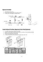
Page 14: ...and bypass the facility 2 Install connector fitting to housing head In outlet in accordance to local plumbing guidelines 3 Mount the housing head onto the bracket 4 Install housing using proper filter wrench 5 Connect the water lines with in outlet port of housing head max 1 25 6 Possible options for the pre filter PP Disruptor GAC KDF 1 Normal 2 Medium 3 Heavy Media Filter Claim Main Valve Feed W...

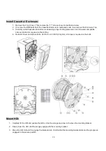
Page 15: ...ater compatible silicone lubricant is required on the O Ring 4 Reinstall Cover and tighten bolts 26 lbf in or 2 2 lbf ft 30 kgf cm of torque is required on the bolts Mount HDI 1 Carefully lift the HDI and positon the HDI so that the prongs are a few inch above the mounting bracket 2 Slowly lower the HDI until the prongs engage with the mounting bracket 3 Move the HDI to the left to engage the brac...

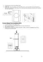
Page 16: ...d procedure and should only be considered when absolutely necessary Process Storage Tank Installation PST 1 Un package the PST from the shipping carton 2 Place an optional PST stand at the desired location for commercial applications 3 Place the tank on the stand 4 Fasten the tank to the wall with a strapping mechanism for safety considerations Important Secure PST as mandated by local plumbing co...

Page 17: ...RTANCE Leave some slack in the tubing Absolutely no tension on the tubing between HDI and the PST 5 Plug the three tubes A B D coming from the bottom of the tank 6 Fill the PST so water is visible from the top opening and then STOP the flow into the tank Do not install the Upper PST Manifold Assembly until PST is almost completely filled with water 7 Install the Upper Manifold Assembly and connect...

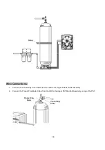
Page 18: ...ct the Conductivity Probe Cable from the HDI to the Upper PST Manifold Assembly 2 Connect the Product Flow Meter Cable from the HDI to the Upper PST Manifold Assembly on top of the PST Product Flow Meter Conductivity Probe Strap ...

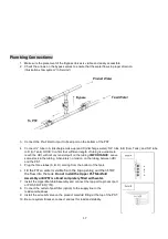
Page 19: ... are no leaks at the fittings connectors system tank top and bottom pre filter or post filter 6 If no leaks connect the electrical cord to the system and turn on the power switch 7 IMPORTANT If a leak is observed bypass the system actuate main bypass depressurize the system using the blue button reset button on the right Hold the button until a click is heard which is opening of the reject solenoi...

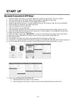
Page 20: ...D and Password as given by homeowner Verify the system is in AQUADASH properly later 10 Select your specific system s parameters 11 Select all of boxes when ready IMPORTANT You have to check all boxes according to the actual situation 12 Run prep cycling on application The prep cycle is 4 minutes long and will automatically stop 13 Press Start on APP 14 Once START is pressed the system will automa...

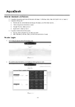
Page 21: ... and the latest version Internet Explorer Version 8 or newer Google Chrome Latest version Apple Safari Latest version Supported mobile device browsers Amazon Silk for Kindle Fire Fire HD Fire HDX Safari Mobile for iPhone iPad and iPod iOS version 6 or newer How to Login 1 Go to http hydrodi monk herokuapp com 2 You will then be directed to your Dashboard listing all your units AquaDash ...

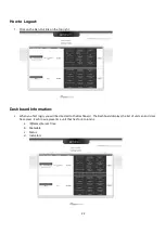
Page 22: ... right Dashboard Information 1 When you first login you will be directed to the Dashboard The Dashboard displays the list of units an End User has access Each row represents a unit that has for 4 columns a ID Name Server Time b Metadata c Status d Indicators ...

Page 23: ...g a ID Unit ID that was generated by the system during creation b Name Name of the Unit given by the Administrator c Server Time Time of the server last sync to the unit 3 Metadata Metadata name of the unit set by the administrator during creation ...

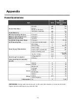
Page 24: ...er Supply Characteristics DC Voltage V 24 DC Amperage A 5A 2 5A Power supply watts 350 Power at peak consumption watts 250 Power at standby mode watts 5 Input AC Voltage VAC 115 230 50 60Hz Daily Energy Consumption 300 gpd 10hr kwh 2 5 Efficiency 85 Ionized substances removed by cassette Cations Sodium 70 Calcium 80 Magnesium 80 Anions Chlorides 80 Sulfates 80 Bicarbonate 80 Nitrates 80 Others Ars...

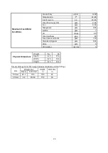
Page 25: ... range 4 9 Total Hardness gpg 23 Total Dissolved Solids ppm 750 Dissolved Organics ppm 0 01 Silica ppm 5 Particulates microns 5 Physical Dimensions Weight lbs 65 Depth inch 17 6 Width inch 16 4 Height inch 22 2 Process Storage Tank The height includes tank base and top fitting Size Weight lbs Height in Diameter in Empty Full Filled 80 Gal 62 7 726 74 3 22 50 Gal 44 459 8 77 2 16 ...

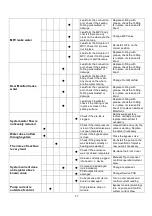
Page 26: ...ll or replace conductivity sensor set with Teflon tape Leak from air relief valve check if the valve was not installed correctly or thread damage Re installation or replace air relief valve with Teflon tape Module leaks water Leak form in outlet port check if the O Ring was not on the position or damage or deformation or particle on the surface Replace O Ring with grease check the O Ring is in pla...

Page 27: ...ck on the sealing surface Replace O Ring with grease check the O Ring is in place is clean and is intact Or replace new Rear Manifold L System water flow is noticeably reduced Check if the pre file is clogged Depressurize system remove cartridge cap and replace internal filter if necessary Check if the inlet pressure is low or the ball valve was not open completely manual flush and verify the valv...

Page 28: ...o switch Re connection or replace new PCBA Pump failed module current will plummet to 0 as dilute compartment is fully de ionized Verify pump operation In process mode when the cut is below the control level statics Pump failed cut will plummet to 0 as dilute compartment is fully de ionized Verify pump operation Module is badly scaled check pressure drop 20 psi per side if scaled replace module or...

Page 29: ...S No Conductivity Read Verify that the sensor is plugged in verify there is water in the line no air bubbles PCB failed to start PCB boot issue 1500uS Verify reading with external tool this can also happen when the process is stopped in the middle of a cycle and the valves switch placing the concentrate loop into the dilute loop which is greater than 1500uS Failure reported by conductivity circuit...
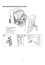
Page 30: ...30 Removing the HDI Rear Enclosure Front Cover 1 Loosen the 4 OWC fitting by wrench and remove it from Rear Manifold 2 Unfasten the five screws used to connect with Frame 3 Remove the Front Cover 1 2 3 ...

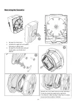
Page 31: ...following in number order 3 Remove the Front Module and pull the Cassette out of Bottom of Module 2 1 3 Special note Care must be taken during installation so that the boss of cassette has to align with in outlet port Radial sealing O Ring have to replace new one when cassette is installed ...

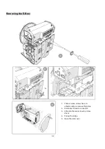
Page 32: ...emoving the E Box 1 There are two screws have to unfasten before remove the E Box 2 Disconnect the wire connector 3 Unfasten the two screws by screw driver 4 Pull up the E Box 5 Open the side cover 3 1 4 5 ...

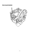
Page 33: ...33 Removing the Manifold ...

Page 34: ...34 Dimensional HDI Drawings Hydronovation Unit Inch ...

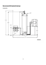
Page 35: ...35 Dimensional HDI System Drawings Connection Unit Inch ...

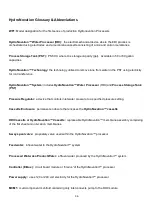
Page 36: ...DI and Process Storage Tank PST Pressure Regulator a device that controls inlet water pressure to a specified pressure setting Cassette Enclosure permanent enclosure that encases the HydroNovation cassette HDI Cassette or HydroNovation Cassette replaceable HydroNovation membrane assembly comprising of the flat sheet anion cation membranes 8 way spool valve proprietary valve used within the HydroNo...

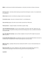
Page 37: ...alled on the bottom of the PST Allows for the feed water connection for the system and tubing connections for discharge water make up and Mod In Mod Out connections to HDI Upper PST Manifold Assembly component that is installed on the top of the PST Allows for the product water connection Product Water Manifold Assembly assembly that is attached to the Product Water Manifold and includes the Air R...

Page 38: ...Novation APP downloaded application from the APP Store HydroNovation APP provides three main functions through Bluetooth between Smartphone and the HDI Processor The functions being Diagnostics Service Settings ...

Reviews: