MaxiCut 5-60 USER MANUAL EDITION 2-05 2012-10-23
9
6. starting - up
6.1 Preliminary steps
Important!
It is essential to determine size measurements and placement in advance in
order to ensure safe placement, running and emergency actions within the
surrounding environment. these conditions should be respected beginning
with the preliminary stages, before cutting begins.
• Place the machine on a steady and flat foundation.
• Check that the cutting blade can rotate freely.
• Check that the cutting blade is tightened.
note !
Before plugging-in the machine, make sure that the line voltage corresponds
to the voltage indicated on the machine.
6.2 operator position
The placement of the machine in relation to the operator´s position must make it
possible to observe the result of the operation and maintain safety conditions.
During this stage, make sure that the start/stop button and safety switch not are
blocked and that there is sufficient visibility and lightning on the machine, the
surrounding area and base.
Warning !
Keep hands clear off the cutting blade area!
Always open the safety hatch and pull the hose with your hand well outside ope
-
ning and then push the hose into opening of the machine, then close the hatch.
Never put your hands thru the cutting blade working area.
6.3 starting - up
Always use safety glasses and ear protection when working with the machine.
Release the safety switch by turning the button clockwise. Select your cutting
speed. Press the START-button. The foot pedal will start the cutting sequence.
Caution!
Check the direction of rotation (the upper edge of the cutting blade shall rotate
towards the back part of the cutting machine). If the machine starts to vibrate
heavily, stop the machine immediately and check the reason for the vibrations.
Summary of Contents for MaxiCut 5-60
Page 1: ...UseR MAnUAL edition 2 05 2012 10 23 serial number MaxiCut 5 60...
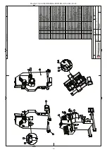
Page 14: ...MaxiCut 5 60 USER MANUAL EDITION 2 05 2012 10 23 14...
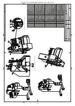
Page 15: ...MaxiCut 5 60 USER MANUAL EDITION 2 05 2012 10 23 15...
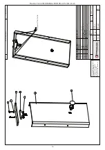
Page 16: ...MaxiCut 5 60 USER MANUAL EDITION 2 05 2012 10 23 16...
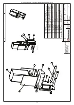
Page 17: ...MaxiCut 5 60 USER MANUAL EDITION 2 05 2012 10 23 17...
Page 18: ...MaxiCut 5 60 USER MANUAL EDITION 2 05 2012 10 23 18...
Page 19: ...MaxiCut 5 60 USER MANUAL EDITION 2 05 2012 10 23 19...
Page 20: ...MaxiCut 5 60 USER MANUAL EDITION 2 05 2012 10 23 20...
Page 21: ...MaxiCut 5 60 USER MANUAL EDITION 2 05 2012 10 23 21...
Page 22: ...MaxiCut 5 60 USER MANUAL EDITION 2 05 2012 10 23 22...
Page 23: ...MaxiCut 5 60 USER MANUAL EDITION 2 05 2012 10 23 23...
Page 24: ...MaxiCut 5 60 USER MANUAL EDITION 2 05 2012 10 23 24...
Page 25: ...MaxiCut 5 60 USER MANUAL EDITION 2 05 2012 10 23 25...
Page 26: ...MaxiCut 5 60 USER MANUAL EDITION 2 05 2012 10 23 26...
Page 27: ...MaxiCut 5 60 USER MANUAL EDITION 2 05 2012 10 23 27...

