background image

Assembly Instructions

5

Step 1

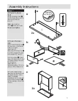
a: 

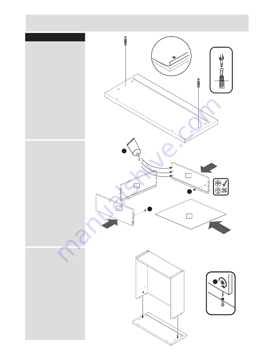
Prepare the drawer 

fronts


Screw 2 locking screw 

B


into the holes shown on the 

back of each drawer 

front 

5

 . 

Note: 

Insert locking 

screw 

B

 as far as shown.

Do not over tighten.

b: 

Prepare the drawer

sides


Insert a small locking nut 

C


into the hole on left drawer 

side 

6

 and right 

drawerside 

8

.

Make sure the ‘arrow’ on 

C

is pointing towards the hole

in the edge of 

6

 and 

8

.

Put drop of glue 

J

 in the 6 

holes of drawersides 

6

 and

8

 before sliding them onto 

the dowels of 

drawerback 

7

.

Slide drawerbase  

0

 in the

grooves of the drawer-unit.

c:

 Turn the drawer wrap 

assembly over and push onto 

the drawer front 

5

 . Use a 

phillips or flatblade 

screwdriver, that is a good fit, 

to turn 24mm locking nut 

C


as far as it will go - more than 

1/2 turn.


5

5

C

C

7

8

10

J

6

C

a:

b:

2x

2x

2x

c:

B

B

If Highgloss, 

Please remove

the protective film!

Summary of Contents for 226/4088

Page 1: ...ssue 3 28 04 16 Important Please read these instructions fully before starting assembly Alternatively call the Spares Helpline on 0370 112 1928 For any other queries please contact the Customer Helpli...

Page 2: ...all the components and tools listed on pages 2 and 3 plastic bags and separate them into their groups Keep children and animals away from the work area small parts could choke if swallowed Make sure y...

Page 3: ...x 2 41 9 x 18 8cm 5 FA4233 P4233 Mirror PS4233 Foldy Back 43 5 x 39 8cm 9 BO253809 Drawer Base x 2 38 6 x 29 9cm 10 BO251209 Right Drawer Side x 2 30 5 x 12cm 8 LA163209 Drawer Back x 2 37 4 x 12cm 7...

Page 4: ...ew x 4 F FK1322 D 12 5mm Pozi screw x 34 H FK1309 Large locking nut x 8 15x12mm Small locking nut x 4 12x10mm I FK1012 15mm 12mm G K Runner left part A x 2 J PM1516LA Glue x 1 Runner left part B x 2 F...

Page 5: ...ke sure the arrow on C is pointing towards the hole in the edge of 6 and 8 Put drop of glue J in the 6 holes of drawersides 6 and 8 before sliding them onto the dowels of drawerback 7 Slide drawerbase...

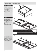
Page 6: ...8 Large locking nuts A into left right side 1 where shown Make sure the arrow on A is pointing towards the hole in the edge of 1 d a b Attaching runners Step 2 a Fix runner left and right side A J an...

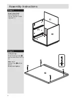
Page 7: ...Use a screwdriver to turn locking nuts A clockwise to lock Position bottom 3 onto foot 4 and fix with 30mm chipboard screw F Screw 24mm locking screws B into bottom 3 Note Insert locking screw Bas far...

Page 8: ...e foldy back 9 into the grooves in left right side 1 Step 6 8 9 1 1 2 a Prepare top Screw 4 locking screw B into the holes shown on top 2 Note Insert locking screw Bas far as shown Do not over tighten...

Page 9: ...rewdriver to turn locking nuts A clockwise to lock Fixate foldy back Turn over chest and slide drawerbase supportsI in corner as shown and fix them using the attached screws Stick the selfadhesive fel...

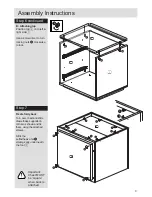
Page 10: ...ners Fix runner left and right side B K and N on left right drawer side 6 and 8 as shown using 12 5mm pozi screw E Step 9 Step 10 Attaching drawer handle Attacht drawer handle L on drawer front 5 as s...

Reviews: