background image

Assembly Instructions

11

Step


17

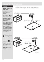
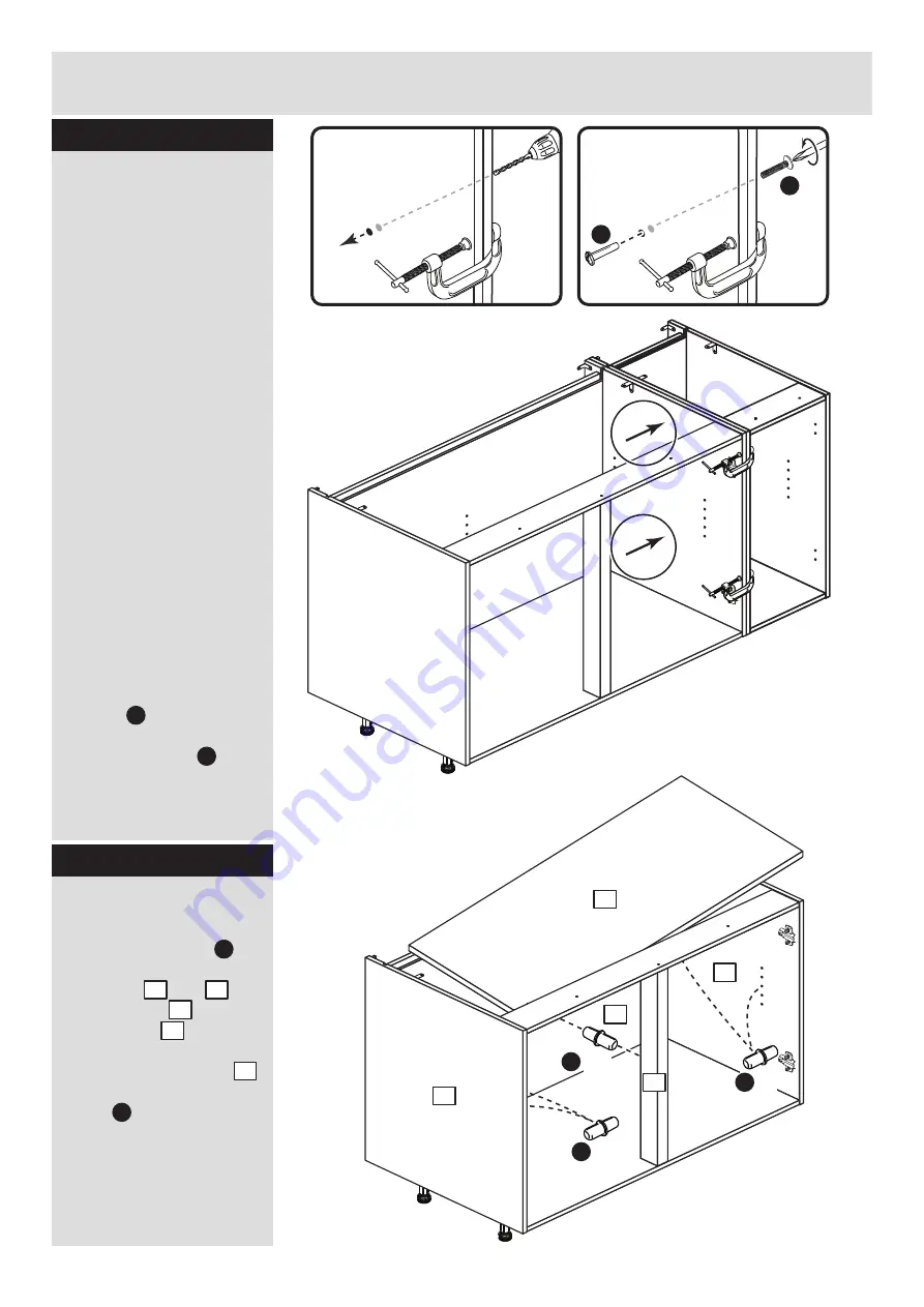
Joining units together

Fittings have been 

supplied so you are able 

to join units together.

Make sure that your first 

unit is level.

Push the other unit up 

against first unit and 

ensure both units are 

level.

Check that the ends are 

flush and in line, then 

clamp them together.

Using a 5mm drill bit, 

drill 2 holes (approximate 

positions shown circled) 

in the side panel into the 

adjoining side panel of 

the other unit.

Push the connecting 

sleeves      into the holes 

and then screw the 

connecting bolts      in 

from the other side. 

G

H

5mm

G

H

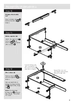
Fit the loose shelf

Insert 6 shelf studs      at 

the required height. 2 in 

each side       and      ,

1 in the back       and 1 in 

the munting      . 

Lower the loose shelf       

down onto the shelf 

studs     .

K

K

5

K

x 2

K

x 2

K

x 2

Step


18

5

1

6

8

2

1

2

6

8

Summary of Contents for 633/2710

Page 1: ...e Cabinet If you need help or have damaged or missing parts call the Customer Helpline 08456 400800 Issue 1 16 08 11 Important Please read these instructions fully before starting assembly hygena 656...

Page 2: ...use opened out unit carton We do not recommend the use of power drill drivers for inserting screws as this could damage the unit Only use hand screwdrivers Safety note If there is any chance of this u...

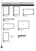
Page 3: ...ting the reference numbers below 5 2 6 4 3 Left Side DPF068A 720 x 560mm Right Side DPF069A 720 x 560mm Loose Shelf DPF083A 968 x 431mm Base DPF082A 969 x 494mm Back DPF085A 979 x 680mm 8 Cross Rail D...

Page 4: ...8 C D Large locking nut F900 x 8 F G H I a I c I d I e I b Ruler Use this ruler to help correctly identify the screws mm 10 20 30 40 50 60 70 80 90 100 110 120 130 140 150 160 170 J K 13mm Screw F63 x...

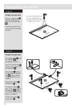
Page 5: ...p edge of the left side about 150mm in from the groove see diagram Secure the bracket using screw Fit another bracket flush to the back edge of the left side about 5mm down from the top edge see diagr...

Page 6: ...els into the holes shown on the right side Fit a bracket flush to the top edge of the right side about 150mm in from the groove see diagram Secure the bracket using screw Fit another bracket flush to...

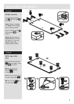
Page 7: ...socket d Push the leg into the leg socket I a I a I a I e I e 3 x 3 I a I a I b I a I a I a I a 3 Prepare the base Insert 4 large locking nuts into the base as shown Note Arrow on locking nut must poi...

Page 8: ...ush the base onto the right side Use a screwdriver to tighten the 2 large locking nuts fitted to the base Note Turn the large locking nuts as far as they will go more than 1 2 a turn B F 3 3 2 C C 2 3...

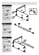
Page 9: ...O 8 8 3 4 O Step 12 3 4 Support this cross rail until the left side has been fitted in the next step 4 Fit a cross rail Push a cross rail onto the right side as shown Use a screwdriver to tighten the...

Page 10: ...assembly Use a screwdriver to tighten the large locking nut fitted to the 2 cross rails and the 2 fitted to the base Note Turn the large locking nuts as far as they will go more than 1 2 a turn 3 1 C...

Page 11: ...stage 6 6 3 3 F F F F F 6 3 Secure the unit to the wall Using the brackets fitted to the back edge of the sides and screw the unit to the wall Fixings are not supplied as they will need to suit the wa...

Page 12: ...amp them together Using a 5mm drill bit drill 2 holes approximate positions shown circled in the side panel into the adjoining side panel of the other unit Push the connecting sleeves into the holes a...

Page 13: ...cross rail as shown Then use 2 screws to screw up through the brackets as shown F E J 4 F F E E Step 20 Prepare the doors Push fit 2 hinges into each door Secure each hinge with 2 screws Note Before s...

Page 14: ...ich holes you need to drill Check that the holes and hinges are in the same place as the diagrams Note We recommend the use of a small piece of waste wood placed behind the hole while drilling to redu...

Page 15: ...the hooks on the hinge arm underneath the front of the hinge plate b Press the front of the hinge arm against the hinge plate until it clicks into place c If you need to seperate the hinge arm from t...

Page 16: ...ews A on hinge plates and move door up or down as required Retighten screw A b Forward and Back adjustment Loosen screw B on hinge arm and move door in or out as required Retighten screw B c Sideways...

Page 17: ...Plinth Pack Fit the plinth After cutting the plinth to the required length offer the plinth up to the unit and using a pencil mark the position of the unit s legs on the back of the plinth Position t...

Page 18: ...e component pages Argos Ltd 489 499 Avebury Boulevard Central Milton Keynes MK9 2NW Step 26 Fit other products to the unit To fit other products to this unit e g worktops etc please follow the instruc...

Page 19: ......

Page 20: ...ALR2653...

Reviews: