background image

7

Assembly Instructions

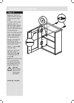
Step 10

Note:

 you may find it 

easier to have help from 
another person at this 
stage.

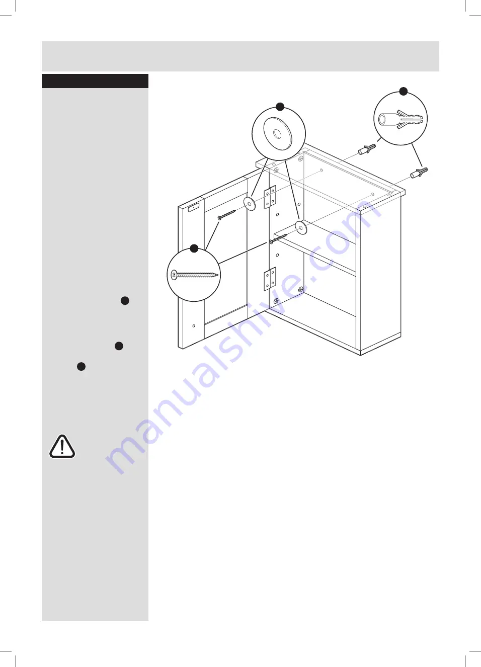
To fix the unit to a wall 
hold the unit in the 
desired position against 
the wall, using a spirit 
level to ensure the unit is 
horizonal/vertical.

Mark the wall through the 
holes in the back panel 
of the unit to establish 
the screw positions.

Set the unit aside and 
drill the wall at the 
mark locations using an 
appropriate drill bit.

Insert 1 x rawl plug 

N


into each hole.

Screw the unit to the 
rawl plug using 2 x 
40mm wall screw 

L

inserted through 2 x 
washer 

M

Note:

 see the back cover 

for more information 
on wall mounting and 
the suitable use of the 
supplied rawl plugs.

Warning:


Before drilling, 
check wall for 
hidden pipes 
and cables.

Assembly complete.

N

L

M

Summary of Contents for 833/4431

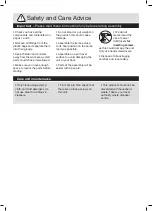
Page 1: ...t 50cm Important Please read these instructions fully before starting assembly Assembly Instructions please keep for future reference 833 4431 Issue 1 23 04 11 If you need help or have damaged or miss...

Page 2: ...ould cause damage Assemble the item as close to its final position in the same room as possible Assemble on a soft level surface to avoid damaging the unit or your floor Parts of the assembly will be...

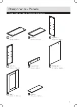
Page 3: ...op x 1 30 w cm x 15 d cm 2 Base x 1 27 w cm x 13 5 d cm 3 Right side x 1 47 h cm x 13 5 d cm 4 Left side x 1 47 h cm x 13 5 d cm 5 Support rail x 1 24 w cm x 6 h cm 6 Back panel x 1 47 8 h cm x 24 8 w...

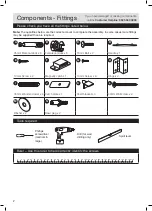
Page 4: ...e camlock x 8 Female camlock x 8 16mm Bolt x 2 Handle x 1 E F G H 14mm Screw x 2 Magnetic catch x 1 10mm Screw x 9 Hinge x 2 I J K L 30mm Wooden dowel x 4 Catch plate x 1 Shelf bracket x 4 40mm Wall s...

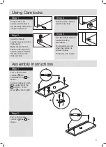
Page 5: ...t the male camlock as directed in the assembly instructions using a screwdriver Step 2 Insert the female camlock as shown in the instructions Note ensure that the arrow on the top of the camlock point...

Page 6: ...mlock E into under side of top base 7 as shown Insert 4 x small wooden dowel D into top shelf 9 as shown Assembly Instructions Step 3 Insert 2 x 30mm wooden dowel I into each end of support rail 5 as...

Page 7: ...en female camlocks with a screwdriver Assembly Instructions Step 6 Connect top 1 to assembly completed at Step 5 as shown and tighten the female camlocks inside the unit with a screwdriver Step 7 Slid...

Page 8: ...atch plate J to door using 1 x 10mm screw G Note catch plate J must be attached with the countersink facing outwards so as to accommodate the screw head Step 9 Insert 4 x shelf bracket K into holes in...

Page 9: ...s in the back panel of the unit to establish the screw positions Set the unit aside and drill the wall at the mark locations using an appropriate drill bit Insert 1 x rawl plug N into each hole Screw...

Page 10: ...8...

Page 11: ...9...

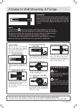
Page 12: ...rom plastic or sometimes wood fiber No 2 General Purpose Wall Plug Aerated Breeze Block Generally aerated blocks should not be used to support heavy loads use a specialist fitting in this case For lig...

Reviews: