background image

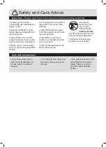
Safety and Care Advice

Important –

 Please read these instructions fully before starting assembly

Care and maintenance

• Check you have all the 
components and tools listed on 
pages 1 and 2. 

• Remove all fittings from the 
plastic bags and separate them 
into their groups.

• Keep children and animals 
away from the work area, small 
parts could choke if swallowed.

• Make sure you have enough 
space to layout the parts before 
starting. 

• Do not stand or put weight on 
the product, this could cause 
damage.

• Assemble the item as close 
to its final position (in the same 
room) as possible.

• Assemble on a soft level 
surface to avoid damaging the 
unit or your floor.

• Parts of the assembly will be 
easier with 2 people.


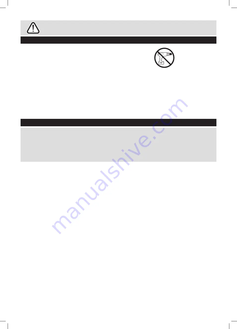
• We do not 
recommend the 
use of power 
drill/drivers 

for 

inserting screws

as this could damage the unit. 
Only use hand screwdrivers.

• Dispose of all packaging 
carefully and responsibly.

• Only clean using a damp 
cloth and mild detergent, do 
not use bleach or abrasive 
cleaners. 

• From time to time check that 
there are no loose screws on 
this unit.

• This product should not be 
discarded with household 
waste. Take to your local 
authority waste disposal 
centre.

Summary of Contents for 833/4455

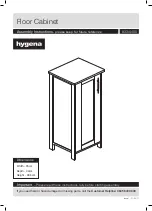
Page 1: ...t 90 5cm Important Please read these instructions fully before starting assembly Assembly Instructions please keep for future reference 833 4455 Issue 1 21 04 11 If you need help or have damaged or mi...

Page 2: ...ould cause damage Assemble the item as close to its final position in the same room as possible Assemble on a soft level surface to avoid damaging the unit or your floor Parts of the assembly will be...

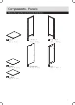
Page 3: ...nels listed below 1 Top x 1 35 w cm x 30 d cm 2 Left side x 1 89 h cm x 28 5 d cm 3 Right side x 1 89 h cm x 28 5 d cm 4 Base x 1 29 w cm x 28 5 d cm 5 Back panel x 1 80 5 h cm x 31 w cm 6 Door x 1 78...

Page 4: ...ck x 8 30mm Wooden dowel x 2 Magnetic catch x 1 E F G H 14mm Screw x 2 Hinge x 2 10mm Screw x 9 Magnetic catch plate x 1 I J K L 16mm Screw x 2 Handle x 1 Shelf bracket x 8 Safety strap x 1 M N O P 10...

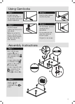
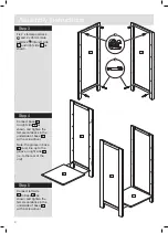
Page 5: ...underside of base 4 as shown Using Camlocks Step 1 Connect the male camlock as directed in the assembly instructions using a screwdriver Step 2 Insert the female camlock as shown in the instructions...

Page 6: ...helf 9 as shown Assembly Instructions Step 3 Fix 2 x female camlock B and 2 x 35mm male camlock A into left side 2 and right side 3 as shown Step 4 Connect base 4 to right side 3 as shown and tighten...

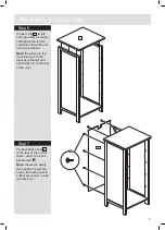
Page 7: ...side of top 10 as shown Step 9 Connect top 10 as shown Tighten female camlocks with a screwdriver Assembly Instructions Step 6 Connect top 1 to left and right sides as shown and tighten the female ca...

Page 8: ...0mm screw G Note catch plate H must be attached with the countersink facing outwards so as to accommodate the screw head Step 9 Insert 8 x shelf bracket K into holes inside the unit at the desired hei...

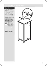
Page 9: ...the safety strap to a wall as shown using 1 x rawl plug Q 1 x washer P and 1 x 35mm screw O Note see the back cover for more information on wall mounting and the suitable use of the supplied rawl plug...

Page 10: ...8...

Page 11: ...9...

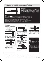
Page 12: ...rom plastic or sometimes wood fiber No 2 General Purpose Wall Plug Aerated Breeze Block Generally aerated blocks should not be used to support heavy loads use a specialist fitting in this case For lig...

Reviews: