5
Assembly Instructions
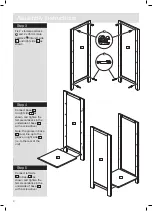
Step 6
Connect top base
7
and top shelf
9
to top
right side
2
.
Tighten female camlocks
in under side of top base
7
with a screwdriver.
Step 7
Connect top left side
1
to exposed ends of top
base
7
and top shelf
9
as shown
Tighten female camlocks
in under side of top base
7
with a screwdriver.
Step 8
Screw 4 x male camlock
A
into the under side of
top
10
as shown.
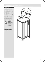
Step 9
Connect top
10
as
shown.
Tighten female camlocks
with a screwdriver.
Assembly Instructions
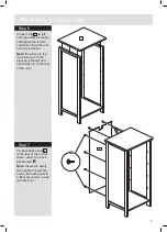
Step 6
Connect top
1
to left
and right sides as shown
and tighten the female
camlocks inside the unit
with a screwdriver.
Note:
the groove in top
must line up with the
grooves in the left and
right sides (i.e. to the rear
of the unit).
Step 7
Connect back panel
5
to the rear of the unit as
shown using 12 x back
panel screw
N
.
Note:
ensure the safety
strap sticks through the
hole in the back panel to
enable securing to a wall
(see Step 10).
1
5
N

