a:
b:
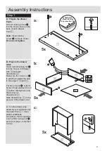
Assembly Instructions
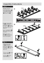
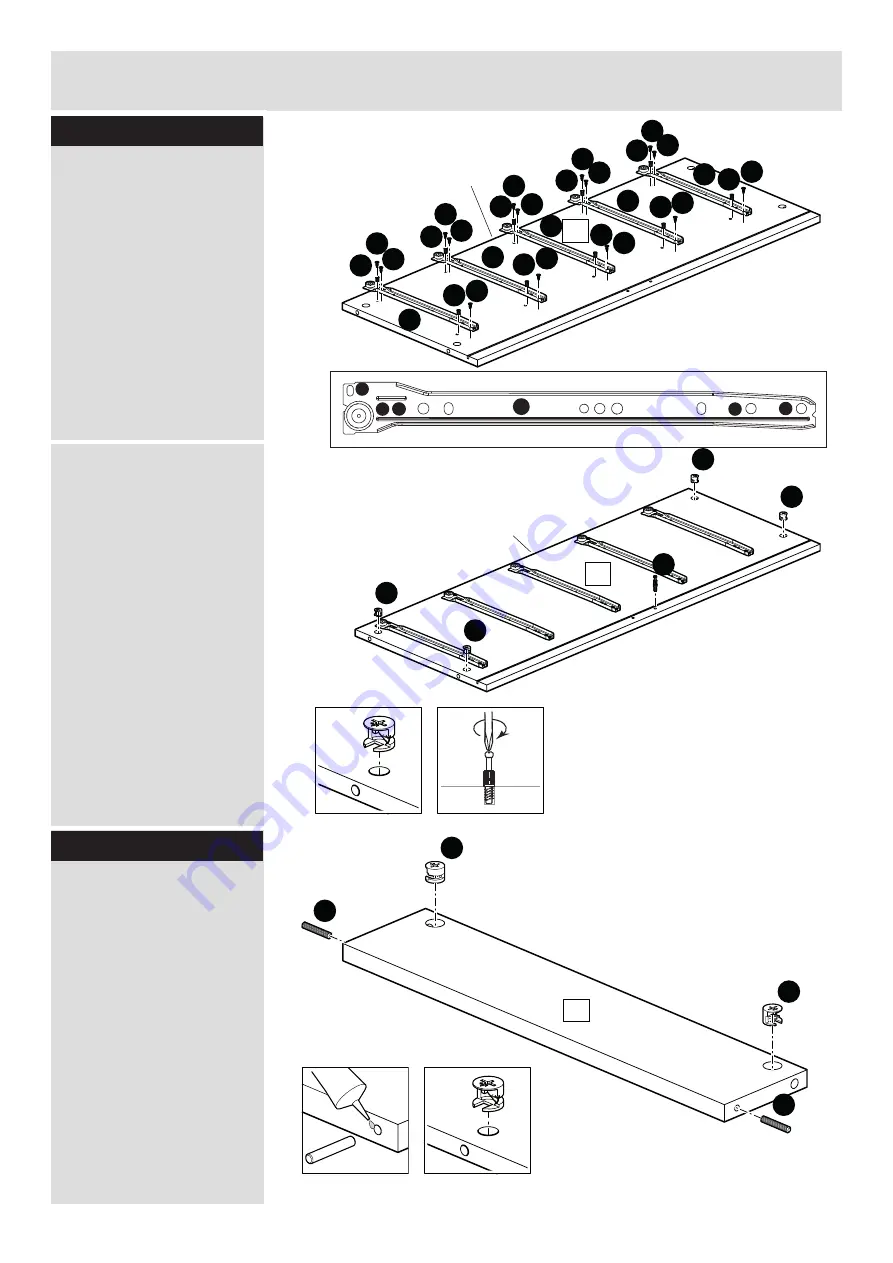
Attaching runners
Step 3
C
C
C
D
D
P
b:
Insert 4 Large locking
nuts
G
into left side
1
where shown. Make sure
the ‘arrow’ on
G
is pointing
towards the hole in the
edge of
1
.
Screw 1 locking screw
E
into the hole shown of the
left side
1
.
Note:
Insert locking
screw
E
as far as shown.
Do not over tighten.
a:
Fix runner left part A
P
on left side
1
as shown
using euro screw drawer
D
and pozi screw
C
.
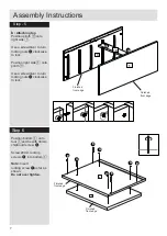
Put drop of glue
K
into the
2 holes of plinth
0
.
Put dowels
H
into the
holes of plinth
0
.
6
Finished
front edge
Finished
front edge
1
C
C
C
C
C
C
C
C
C
C
C
C
C
C
C
D
D
D
D
D
D
D
P
P
P
P
P
D
D
D
G
G
G
G
1
E
Step 4
Insert 2 Large locking
nuts
G
into plinth
0
where shown. Make sure
the ‘arrow’ on
G
is pointing
towards the hole in the
edge of
0
.
H
H
10
G
G

