background image

L

3

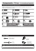
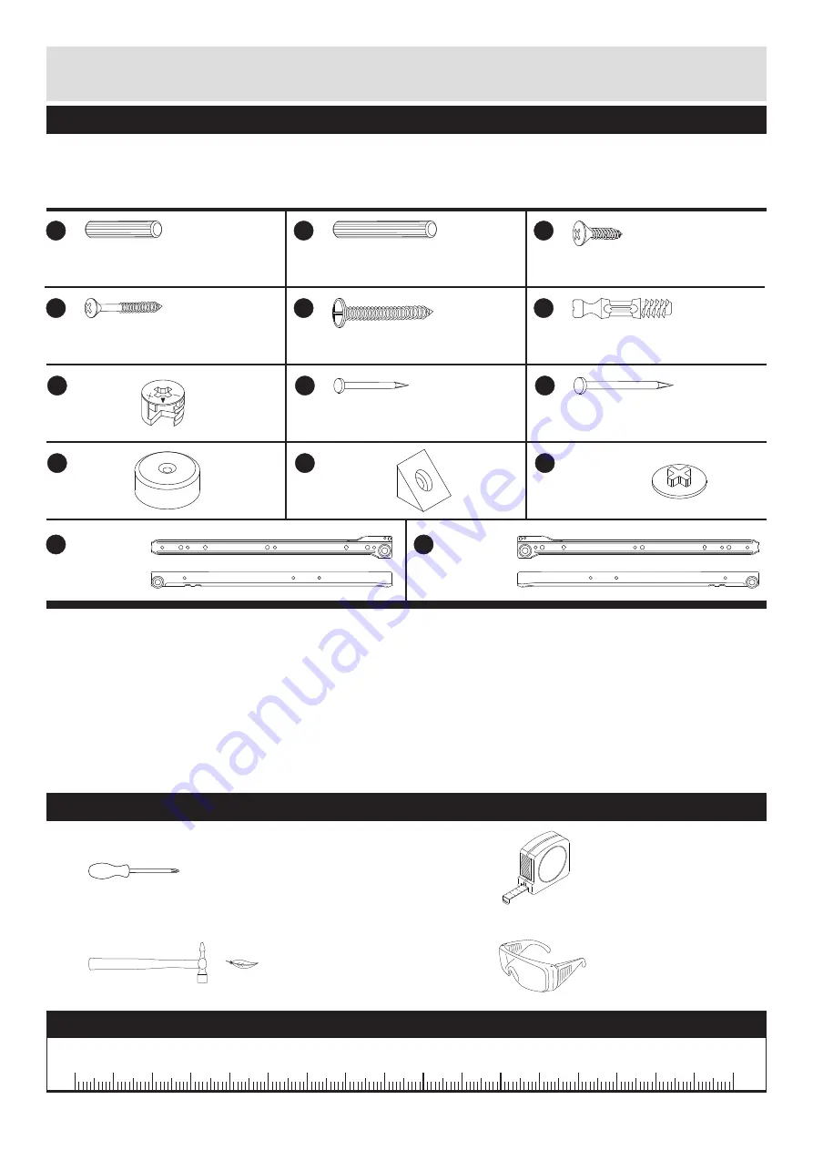
Please check you have all the fittings listed below

Note:

The quantities below are the correct amount to complete the assembly. In some cases more

fittings may be supplied than are required.

Ruler

- Use this ruler to help correctly identify the screws

0

5

10

15

20

25

30

35

40

45

50

55

60

65

70

75

80

85

90

95

100 105 110 115 120 125 130 135 140 145 150 155 160 165 170

Tools required

Phillips screwdriver
(small & medium)

Eye protection
(when using a
hammer or glue)

Small
hammer

Ruler/tape
measure

2

m

Components

- Fittings

If you have damaged or missing components,
call the

Customer Helpline: 08456 400 800

N

A

B

C

Ø 6X30 Wooden dowel x 24

D

E

F

I

G

H

J

Right runner
x 2 pair

Left runner
x 2 pair

Plastic
cap x 14

K

M

Plastic
bracket x 4

Plastic
feet x 4

Nail x 4

Nail x 30

Locking
nut x 16

Metal dowel x 16

40mm Screw x 4

20mm Screw x 4

14mm Screw x 16

Ø 6X50 Wooden dowel x 2

Summary of Contents for Hamlin 145/5726

Page 1: ...r future reference Issue 1 28 10 13 152 5340 If you need help or have damaged or missing parts call the Customer Helpline 08456 400 800 Important Please read these instructions fully before starting a...

Page 2: ...wer drill drivers for inserting screws as this could damage the unit Only use hand screwdrivers Parts of the assembly will be easier with 2 people Dispose of all packaging carefully and responsibly Do...

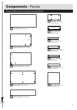
Page 3: ...3cm 3 Left side panel 72 x 43cm Top Top 6 Middle wall panel 17 5 x 43cm 12 Drawer bottom x 2 39 8 x 38 5cm 11 Top front frame x 2 42 6 x 6cm 7 Drawer front x 2 43 6 x 15cm 8 Drawer back x 2 37 2 x 8cm...

Page 4: ...130 135 140 145 150 155 160 165 170 Tools required Phillips screwdriver small medium Eye protection when using a hammer or glue Small hammer Ruler tape measure 2 m Components Fittings If you have dama...

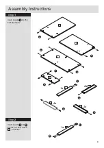
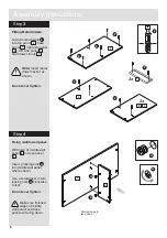
Page 5: ...Step 1 Assembly Instructions 4 Insert dowels into the indicated parts A A B A A A A A A A A 2x 1x 2x 2 3 4 6 9 10 11 8 2x A A 1x 11 Step 2 Insert dowels and into the top front frame as shown A B 11...

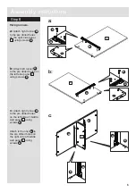
Page 6: ...hown Do not over tighten F F F F F F 2 3 4 1 7 2x 2x 1 4 2 3 7 G G 4 6 G G Fixing middle wall panel With help fit middle wall panel to base panel Insert 2 locking nuts into middle wall panel where sho...

Page 7: ...B c Attach right runner to the pre drilled holes on the left side of middle wall panel using screws Attach left runner to the pre drilled holes on the right side of middle wall panel using screws B B...

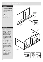
Page 8: ...t right side panel and left side panel to base panel and top front frames Insert 4 locking nuts into base panel where shown Use a screwdriver to turn locking nuts clockwise to lock Do not over tighten...

Page 9: ...to the cabinet Insert 4 locking nuts into side panels and 2 locking nuts into middle wall panel where shown Use a screwdriver to turn locking nuts clockwise to lock Do not over tighten After screwing...

Page 10: ...anel using nails After attach back panel with help carefully lay down the product 5 H Step 10 Attach plastic feet Attach p in lastic feet the bottom edge of the right and left side panels using nails...

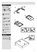
Page 11: ...ise to lock Do not over tighten After screwing locking nuts insert plastic caps Repeat step 11 for the other drawer Drawer assembly a Fix drawer sides and to the drawer back using screws b Slide drawe...

Page 12: ...f the drawers using screws as shown Make sure runners are correctly positioned according to the diagram prior to fixing Step 14 Hook the wheels of the runner on the back of the drawers over the wheels...

Reviews: