background image

LP 056.96.133

A Guide to Wall Mounting & Fixings

IMPORTANT:

When drilling into walls always check that there are no 
hidden wires or pipes etc. Make sure that the screws 
and wall plugs being used are suitable for supporting 
your unit. Consult a qualified tradesperson if you are 
unsure.

HINTS:

1) General Rule 

 Always use a larger screw and wall plug if you are not sure.

2) Ensure you use the recommended drill bit to match the wall plug and hole size.
3) Ensure you drill the hole horizontally, do not force the drill or enlarge the holes.
4)  Take extra care when drilling high walls, ceilings and ceramic tiles.  

Ensure the plus is fitting below the ceramic tile to avoid splitting or cracking.

5) Ensure wall plugs are well fitted and are a tight fit in the drilled hole.

Types of Wall

You  can  use  one  of  the  following 
types  of  wall  plug  if  your  walls  are 
made of brick, breeze block, concrete, 
stone,wood or plaster board. 

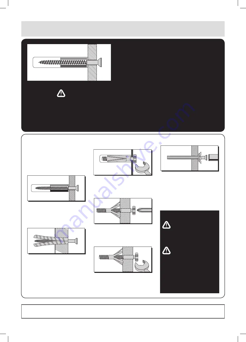
No.1 “ Standard” Wall Plug 

General Wall Materials

These  come  in  various  sizes  and  are 
made from plastic or sometimes wood 
fiber.

No.2 “ General Purpose” Wall Plug 

Aerated / Breeze Block

Generally  aerated  blocks  should  not 
be used to support heavy loads, use a 
specialist fitting in this case.
For  light  loads,  a  General  Purpose 
Plug can be used.

No.3 “ Shield Anchor” Wall Plug 

Heavy loads

For use with heavier loads such as TV 
&  HiFi  speakers  and  satellite  dishes 
etc.

No.4 “Cavity Fixing” Wall Plug

For  use  with  plaster  board  partitions 
or hollow wooden doors.

No. 5 “ Cavity Fixing - Heavy Duty” 

Wall Plug

For  use  when  fitting  or  supporting 
heavy  loads  such  aas  shelving  wall 
cabinets, coat racks.

No.6 “Hammer Fixing” Wall Plug

For  use  with  walls  stuck  with  plaster 
board.  The  hammer  fixing  allows  it 
to be fixed to the wall rather than the 
plaster board. Always check the fixing 
is secure to the retaining wall.

CARE AND MAINTENANCE

 SAFETY

Always  check  the  fitting  and 
location to ensure your safety in 
and around the home.

 FITTING

From  time  to  time  check  the 
fitting  to  ensure  the  wall  plugs 
or screws do not become loose.

If you need help or have damaged or missing parts, call the

 Customer Helpline: 0845 640 0800

Home Retail Group, 489-499 Avebury Boulevard, Saxon Gate West, Central Milton Keynes, Bucks, MK9 2NW

Summary of Contents for Tallboy 833/4448

Page 1: ...9 5cm Important Please read these instructions fully before starting assembly Assembly Instructions please keep for future reference 833 4448 Issue 1 26 04 11 If you need help or have damaged or missi...

Page 2: ...ould cause damage Assemble the item as close to its final position in the same room as possible Assemble on a soft level surface to avoid damaging the unit or your floor Parts of the assembly will be...

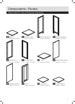
Page 3: ...m x 28 5 d cm 4 Bottom right side x 1 89 h cm x 28 5 d cm 5 Top left side x 1 77 5 h cm x 28 5 d cm 6 Top right side x 1 77 5 h cm x 28 5 d cm 7 Top x 1 35 w cm x 30 d cm 8 Bottom back panel x 1 80 2...

Page 4: ...amlock x 8 30mm Wooden dowel x 4 E F G H 14mm Screw x 2 Magnetic catch x 1 10mm Screw x 9 Hinge x 2 I J K L 16mm Screw x 2 Handle x 1 Magentic catch plate x 1 Back panel screw x 22 M N O P 35mm Screw...

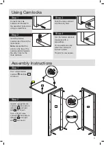
Page 5: ...s Step 1 Connect the male camlock as directed in the assembly instructions using a screwdriver Step 2 Insert the female camlock as shown in the instructions Note ensure that the arrow on the top of th...

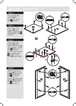
Page 6: ...small female camlock C into underside of 2 x top shelf 11 as shown Step 4 Fix 4 x 35mm male camlock A and 2 x 30mm wooden dowel D into underside of top 7 as shown Step 5 Fix 4 x 35mm male camlock A an...

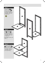
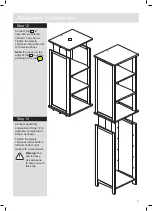
Page 7: ...er side of top 10 as shown Step 9 Connect top 10 as shown Tighten female camlocks with a screwdriver Assembly Instructions Step 7 Connect base 1 to bottom right side 4 as shown and tighten the female...

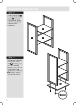
Page 8: ...shown and tighten the female camlocks in underside of shelves with a screwdriver Step 11 Fix assembly completed at Step 10 to middle shelf 2 as shown using 4 x 35mm screw M Note the male camlocks and...

Page 9: ...t with a screwdriver Note the groove in the edge of top 7 must be pointing to the rear Step 13 Connect assembly completed at Step 12 to assembly completed at Step 8 as shown Tighten the female camlock...

Page 10: ...8 Assembly Instructions Step 14 Fix bottom back panel 8 and top back panel 9 to the rear of the unit using back panel screws L as shown 8 9 L...

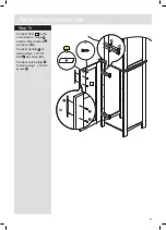
Page 11: ...ons Step 15 Connect door 10 to the unit using 2 x hinge H and 8 x 10mm screw G as shown b Connect handle J to door using 2 x 16mm bolt I as shown c Connect catch plate K to door using 1 x 10mm screw G...

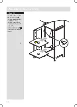
Page 12: ...ions Step 16 Insert 8 x shelf bracket P into holes inside the unit at the desired heights ensuring that each set of shelf brackets are level with each other Set 2 x internal shelf 12 onto shelf bracke...

Page 13: ...rew N Fix the other end of the safety strap to a wall using 1 x rawl plug S 1 x washer R and 1 x 35mm wall screw Q Note see the back cover for more information on wall mounting and the suitable use of...

Page 14: ...12...

Page 15: ...13...

Page 16: ...rom plastic or sometimes wood fiber No 2 General Purpose Wall Plug Aerated Breeze Block Generally aerated blocks should not be used to support heavy loads use a specialist fitting in this case For lig...

Reviews: