background image

Assembly lnstructions

11

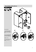
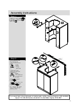
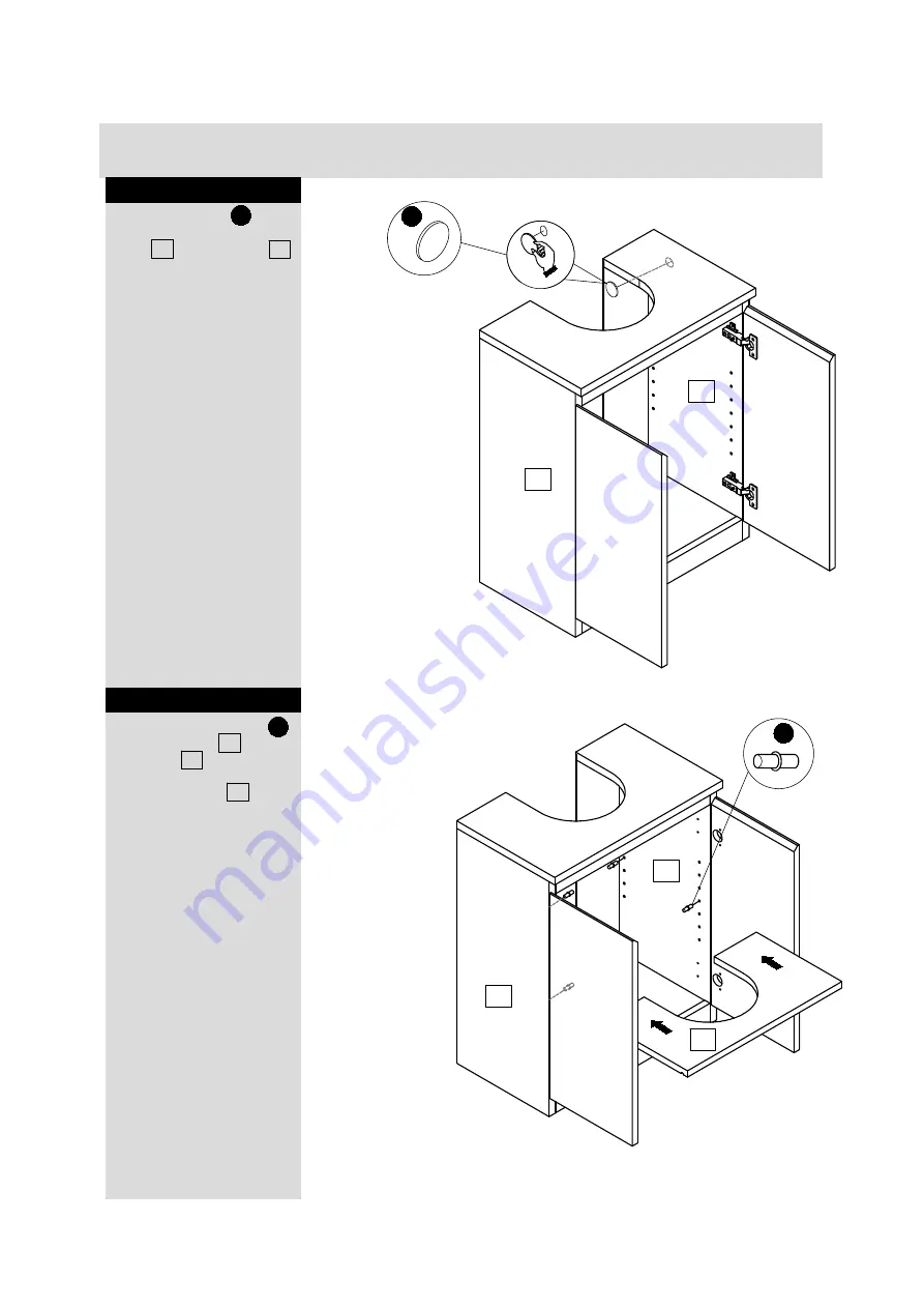
Step 9

Step 10

1.Use 4 x stickers        to

cover camlocks on 2x side
panel  3   and left upright  5
as shown.

5

3

H

H

10

5

3

E

1.Insert 4 x shelf holders

to 2 x side panel  3   and

left upright  5  and right  .

2.Attach 4x panel  10  and
onto shelf holder as shown.

E

Summary of Contents for Underbasin 527/9142

Page 1: ...basin 527 9142 Dimensions Width 48cm Depth 28cm Height 60cm Issue 1 21 03 15 Important Please read these instructions fully before starting assembly Assembly lnstructions please keep for future refere...

Page 2: ...the below steps Do not allow children to climb or hang on the furniture Do not place heavy items in the top drawers Do not place heavy items on top of the furniture unless the furniture has been desig...

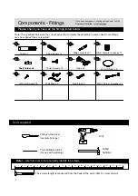
Page 3: ...Components Panels Please check you have all the panels listed below 2 If you have damaged or missing components call the Customer Helpline 1 2 4 6 7 9 3 5 8 10...

Page 4: ...7mm Suitable drill bit for use with wall plug Small hammer Ruler Use this ruler to help correctly identify the screws 0 The screws length is measured from the head to the point 30mm screw shown 5 10...

Page 5: ......

Page 6: ...Assembly lnstructions Step 1 Fitting male camlocks 1 Insert 11 x male camlocks into Panel 2 3 5 6 and tighten using a suitable screwdriver c 5 2 3 5 6 C...

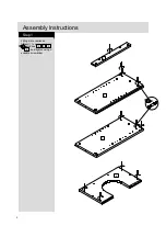
Page 7: ...Assembly lnstructions Step 2 1 Glue and insert 12 x dowels into panel 1 2 3 4 5 as shown B 6 B 2 3 5 1 4 A...

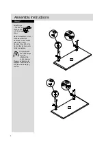
Page 8: ...ock Please refer to the Using Camlocks section at the front of this instruction for further assistance D D Step 4 Matt side A 1 Glue holes in right side panel 3 connect back panel 1 2 and front panel...

Page 9: ...Please refer to the Using Camlocks section at the front of this instruction for further assistance D D 6 A 5 3 Step 6 1 Glue holes in right side panel 7 X2 connect back panel 1 3 and front panel 5 6 t...

Page 10: ...wdriver to turn the female camlock clockwise to lock Please refer to the Using Camlocks section at the front of this instruction for further assistance Very Important The friction stays must be attach...

Page 11: ...x screw as shown F E Hinge adjustment a To move the top panel up or down loosen screws shown and move top panel to suit b To move the top panel in or out loosen screws shown and move top panel to sui...

Page 12: ...p 10 1 Use 4 x stickers to cover camlocks on 2x side panel 3 and left upright 5 as shown 5 3 H H 10 5 3 E 1 Insert 4 x shelf holders to 2 x side panel 3 and left upright 5 and right 2 Attach 4x panel...

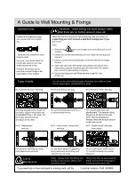
Page 13: ...iling check wall for hidden pipes and cables 3 Drill hole and insert 2 x wall plug 4 Secure the other end of the 2 x strap to the wall with 2 x washer screw Note To hide the strap behind the unit dril...

Page 14: ......

Reviews: