background image

Assembly Instructions

17

Step


22

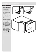
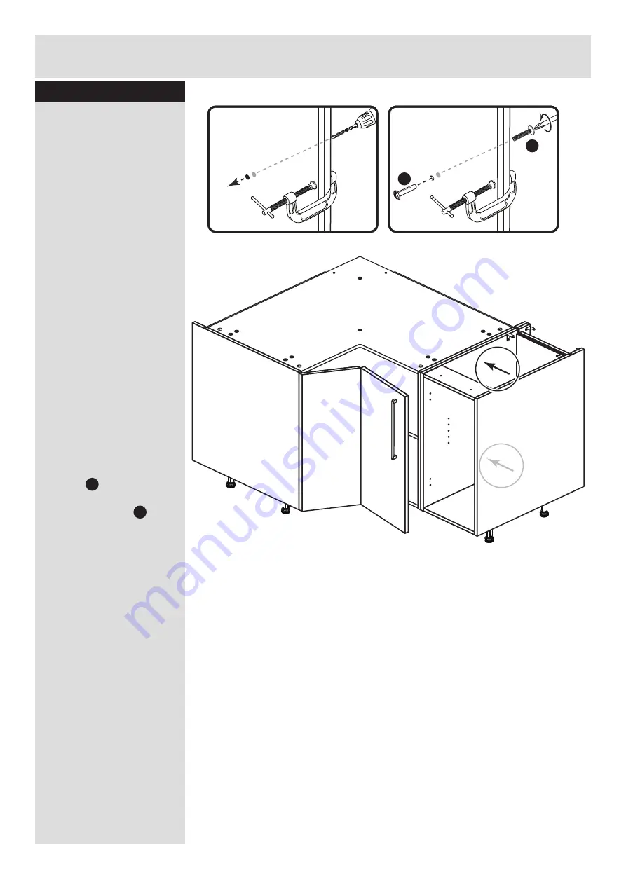
Joining units together

Fittings have been 

supplied so you are able 

to join units together.

Make sure that your first 

unit is level.

Push the other unit up 

against first unit and 

ensure both units are 

level.

Check that the ends are 

flush and in line, then 

clamp them together.

Using a 5mm drill bit, 

drill 2 holes (approximate 

positions shown circled) 

in the side panel into the 

adjoining side panel of 

the other unit.

Push the connecting 

sleeves      into the holes 

and then screw the 

connecting bolts      in 

from the other side. 

G

H

5mm

G

H

Summary of Contents for Valencia 656/5800

Page 1: ...ence If you need help or have damaged or missing parts call the Customer Helpline 08456 400800 Issue 2 05 08 14 Important Please read these instructions fully before starting assembly hygena 656 5800...

Page 2: ...t level surface to avoid damaging the unit or your floor use opened out unit carton We do not recommend the use of power drill drivers for inserting screws as this could damage the unit Only use hand...

Page 3: ...Helpline 08456 400800 quoting the reference numbers below Top Base DPF136A 800 x 800mm x 2 4 2 Left Right Back DPF139A 630 x 717mm x 2 Loose Shelf DPF137A 798 x 798mm 3 Back DPF138A 272 x 688mm Left R...

Page 4: ...tal dowel F901 x 8 C D Large locking nut F900 x 8 F G H I a I c I d I e I b J K 13mm Screw F63 x 8 E 13mm Screw F79 x 2 Connecting Sleeve F432 x 2 19mm Connecting bolt F461 x 2 L M N O Q N P 25mm Scre...

Page 5: ...this way fit the hinge plates to the left side If you would like your door to open this way fit the hinge plates to the right side H 2 Q Prepare the left side Refer to step 1 and if required fit 2 hin...

Page 6: ...ully against the panels Fit a bracket flush to the top and back edge of the right side Secure the bracket using screw 4 B 4 J J 4 E C C C C A A A A A A Prepare the top and base Insert 4 large locking...

Page 7: ...centre plug on each leg socket d Push the leg into the leg socket I a I a I a I e I e 1 x 3 I a I a I b I a I a I a I a I a I a 4 1 Join the right side and base Push the base onto the right side Use...

Page 8: ...back Push the back onto the base and secure with screw 1 3 Fit the top Push the top onto the right side and back Use a screwdriver to tighten the 2 large locking nuts fitted to the top Note Turn the l...

Page 9: ...base and top Use a screwdriver to tighten the 4 large locking nuts fitted to the base and top Note Turn the large locking nuts as far as they will go more than 1 2 a turn 1 1 1 1 4 1 1 C C 4 Insert t...

Page 10: ...s 9 Step 12 Step 13 F Secure the left back Secure the left back with 6 screws through its pre drilled holes into the base and top F F F F F F Fit the left back Slide the left back along the groove in...

Page 11: ...t 7 shelf studs at the required height Lower the loose shelf down onto the shelf studs M M M M M 2 2 2 Fit the right back Slide the right back along the groove in the right side Secure the right back...

Page 12: ...a door making sure that they face the same way as the diagram b Push fit 2 cantilevered hinge arms into the door Secure each hinge arm with 2 screws Note Before securing with the screws make sure that...

Page 13: ...nderneath the front of the hinge plate b Press the front of the hinge arm against the hinge plate until it clicks into place c If you need to seperate the hinge arm from the hinge plate press the butt...

Page 14: ...other door to be the hinged door Push fit 2 bent hinge arms into the other door Secure each hinge arm with 2 screws Note Before securing with the screws make sure that the hinges are positioned at 90...

Page 15: ...iece of waste wood placed behind the hole while drilling to reduce the possibility of any breakout Using the pilot hole in the rear face of the door drill through the holes indicated opposite using a...

Page 16: ...ont of the hinge arm against the hinge plate until it clicks into place c If you need to seperate the hinge arm from the hinge plate press the button at the end of the hinge arm and lift it off of the...

Page 17: ...Assembly Instructions 16 Step 21 Fit the soft close unit Push a soft close unit onto each cantileved hinge arm until it clicks into place K P K P...

Page 18: ...unit up against first unit and ensure both units are level Check that the ends are flush and in line then clamp them together Using a 5mm drill bit drill 2 holes approximate positions shown circled in...

Page 19: ...inth I c I c I d Plinth I e I e Fit the plinth After cutting the plinth to the required length offer the plinth up to the unit and using a pencil mark the position of the unit s legs on the back of th...

Page 20: ...ALR2656...

Reviews: