background image


                                                                                                                                              Page 11

4.

Operation and Installation

4.1

Mode of Operation

The HygroMatik steam humidifier utilizes the conductivity nor-
mally present in tap water for steam production. Electrodes
inside an enclosed steam cylinder are immersed directly into the
tap water. They are connected to the alternating current.

The conductivity of the water generates an electric current
between the electrodes. In this way, the electric power supplied
is converted directly into heat without energy loss.

The amperage is a function of the available voltage, the
immersed electrode surface area, the average distance between
the electrodes and the water conductivity. The steam output of
the humidifier is determined by electric power usage, which is
regulated by increasing or decreasing the immersed surface
area of the electrodes.

Concurrently, a self-regulating control keeps conductivity within
a specified range. 

The steam produced has a temperature of about 100°C with
minimal excess pressure ("pressureless steam"). It is largely
free of minerals and germ-free. Mineral deposits typically remain
behind in the cylinder.

4.2

Installation and Operation

By pressing the control  switch („Pos. I”) the humidifier is turned
on. When the controller specifies an increase in humidity, the
main contactor is switched on and the electrodes (48) are sup-
plied with power. The water inlet solenoid valve (25) feeds water
into the steam cylinder (16+19).

As soon as the electrodes are immersed, the current begins to
flow. The water is now heated. When the pre-selected output is
reached, the control turns off the solenoid valve and interrupts
the water supply.

After a short heating up period, the water between the elec-
trodes begins to boil and vaporize. The vaporization lowers the
water level in the steam cylinder, reducing the output provided.
The inlet solenoid valve, equipped with a fine mesh filter, inter-
mittently admits fresh water.

Humidifier power usage is continuously monitored. With a cold
start-up, the nominal current increases to 125% in order to
achieve quick-start output parameters. This activates the elec-
tronic overflow limiter which causes a partial draining of the cyl-
inder. This reduces the immersed surface area of the electrodes,
lowering power usage.

Summary of Contents for C01 KIT

Page 1: ...CompactLine KIT Electrode Steam Humidifier Manual...

Page 2: ...be reprogrammed to fit the special requirements of a particular area In addition it is possible to install a plastic star in the cylinder in order to increase the life span of the electrodes or to pr...

Page 3: ...onment 14 5 1 1 Fitting 15 5 1 2 Equipment Dimensions CompactLine KIT 16 5 2 Fan Unit optional 17 5 2 1 Fan Unit Type VG 17 5 3 Absorption Distance BN 18 5 3 1 Determining the Absorption Distance 18 5...

Page 4: ...1 Cleaning the Steam Cylinder 43 8 1 2 Electrode Wear 45 8 2 Replacing Electrodes 46 8 3 Cleaning the Blow Down Pump 48 8 4 Cleaning the Water Inlet Solenoid Valve 49 8 5 Chekking Cable Connections an...

Page 5: ...ne Fax 49 0 4193 895 33 e mail hot1 HygroMatik de For all technical questions or spare parts orders please be pre pared to provide unit type and serial number see name plate on the unit 1 1 Directions...

Page 6: ...shold Warning HygroMatik steam humidifiers emit steam with a tem perature of 100 C The steam may not be inhaled directly The HygroMatik Steam Humidifier is not designed for outdoor fit ting 1 2 Typogr...

Page 7: ...sible location If the product is resold turn the documenta tion over to the new operator If the documentation is lost please contact HygroMatik Versions in Other Languages These operating instructions...

Page 8: ...steps must be taken to protect against ESD Reminder Materials and consumables must be handled and or disposed of as required by law Note Appears before explanations or cross references which refer to...

Page 9: ...it components from power supply prior to mainte nance or repair work Attaching or installing additional components is permitted only with the written consent of the manufacturer Electrical Work on the...

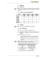
Page 10: ...match those specified in the order and delivery documents and the equipment is complete and all parts are in perfect condition Note In case of damage during shipment or missing parts immediately noti...

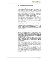
Page 11: ...f minerals and germ free Mineral deposits typically remain behind in the cylinder 4 2 Installation and Operation By pressing the control switch Pos I the humidifier is turned on When the controller sp...

Page 12: ...r 6 vent pipe 10 max water level sensor electrode 14 water drain discharge 16 top part of steam cylinder 17 o ring cylinder flange 18 cylinder flange and o ring 19 lower part of cylinder 25 solenoid v...

Page 13: ...al deposits settle in the open area below the electrodes and are removed through periodic maintenance The blow down pump itself has wide openings and can flush out smaller pieces of mineral deposit Th...

Page 14: ...ed 80 RH An Installation in a closed room requires aeration and if neccessary temperature conditioning in order to reach the above mentioned environmental conditions The minimum clearances indicated i...

Page 15: ...here is no suitable wall it is recommended that the equipment is installed on brackets which can be embedded in the floor Note The C45KIT cannot be used for wall mounting The instal lation has to be d...

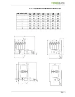
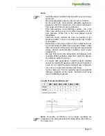
Page 16: ...n mm C01 KIT C02 KIT C06 KIT C10 KIT C17 KIT C30 KIT C45 KIT x 270 270 270 270 328 328 330 y 310 287 365 413 575 575 615 z 175 175 175 175 254 254 316 a 27 27 27 27 47 47 49 b 35 35 35 35 55 55 30 c 1...

Page 17: ...not touch the fan during operation 5 2 1 Fan Unit Type VG Install the fan unit over the steam humidifier When employing multiple fan units do not exceed a maximum distance of 5 m from the steam humidi...

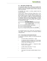
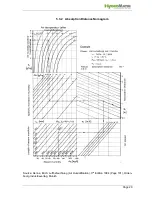
Page 18: ...ated as a multiplier of the absorption distance BN The absorption distance has no fixed value but depends on many factors These are depicted in the absorption distance nomogram below 5 3 1 Determining...

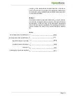
Page 19: ...he parameters enumerated above into the respective quadrants The resulting point of inter section indicates the value of the desired absorption distance BN Notes x1 _______________________________ g k...

Page 20: ...Page 20 5 3 2 Absorption Distance Nomogram Source Henne Erich Luftbefeuchtung Air Humidification 3rd Edition 1984 Page 101 Olden bourg Industrieverlag Munich...

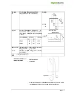
Page 21: ...e the total hight of the duct Minimum distances in order to avoid condensation Lmin 210mm distance steam manifold next steam mani fold L4min 120mm distance lowest steam manifold duct bot tom L5min 120...

Page 22: ...ly Air flow very flat By tilting the steam manifold 30 45 towards the air flow direction the mini mum upper clearance can be reduced to 70mm min distances H1 mm H2 mm 30 45 DN25 182 168 225 DN40 193 1...

Page 23: ...ed Shown instal lation and position dimensions are based on experimental values Special environmental conditions could require adjustments We note that the German Association of Engineers VDI Guidelin...

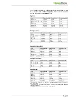
Page 24: ...0 1xDN40 DN40 DN12 HY45 HY60 2xDN40 2xDN40 2xDN12 HY90 HY116 4xDN40 4xDN40 4xDN12 Type Steam Manifold Steam Hose Condensate Hose C1 C17 1xDN25 DN25 DN12 C10 DS C17DS for SPA 1xDN40 DN40 DN12 C22 C30 1...

Page 25: ...on two steam manifolds the T pieces for the steam and condensate hose should be installed near the manifolds If the installation is carried out in this way only one steam hose is necessary for the mai...

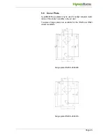
Page 26: ...k flange plates may be used to neatly complete instal lation of the steam humidifier in the air duct Two piece flange plates are available for the DN25 and DN40 steam manifolds flange plate DN25 E 260...

Page 27: ...Page 27 5 7 Drill Pattern 5 7 1 Drill Pattern DN25 not to scale Note Due to variable print media the dimensions are not to scale...

Page 28: ...Page 28 5 7 2 Drill Pattern DN40 not to scale Note Due to variable print media the dimensions are not to scale...

Page 29: ...ed there is enough space If the steam manifold is positioned lower than 500 mm above the steam humidifier The condensate must be drained separately To prevent steam loss lay a loop at least 200 mm in...

Page 30: ...se with rising slope Steam manifold is positioned below the steam humidifier Lay steam hose at a height of at least 400 mm and then connect to the steam manifold with a constant fall Lay condensate ho...

Page 31: ...Page 31 Detail X wrong...

Page 32: ...The best position is just above the steam humidifier Installation of Steam Solenoid Valve 5 11 Unit Installation Check Attention This unit may only be operated by qualified and prop erly trained perso...

Page 33: ...ts are required In this case please contact HygroMatik The water supply temperature may not exceed 40 C Water installation pressure 1 10 bar 100 x 103 to 100 x 104 pascal Blow down water must be able...

Page 34: ...conductiv ity is typically higher at operating temperature Install a Hygro Matik cylinder star to extend the service life of the electrodes 6 2 Water Supply Install a shut off valve SV in the supply...

Page 35: ...e level Please note Do not bend the drain hose Install discharge line and drain pipe made from temper ature resistant material to 95 C Install water discharge as follows Loosely insert a length of 1 1...

Page 36: ...e following water installation checklist Are all screws and clamps properly tightened Is the water supply pipe flushed Was the water installation correctly installed Can the blow down water drain free...

Page 37: ...nect power supply before installation and protect against restart Verify the absence of electric current Make sure the unit is switched off before installing or removing the display plate or basic PCB...

Page 38: ...x 400V 3Phase N HY60 HY116 2 x 400V 3Phase N Type Main Power Supply CompactLine 1 x 400V 3Phase N Type Main Power Supply MS5 MS10 1 x 400V 3Phase N MS5 1 x 230 1Phase N Type Main Power Supply C01KIT...

Page 39: ...5 A 3 x 35 A C45 48 8 A 3 x 63 A C58 62 8 A 3 x 63 A Type Power Usage Circuit Protection MS5 230V 1 N 15 7 A 1 x 16 A MS5 400V 3 N 5 4 A 3 x 6 A MS10 400V 3 N 10 8 A 3 x 16 A Type Power Usage Circuit...

Page 40: ...e unit and one for the control 7 4 Electrical Installation Checklist Perform electrical installation checks in compliance with cus tomer site requirements and public power utility regulations Is the p...

Page 41: ...witch off the unit before maintenance and protect against restart After maintenance work have qualified personnel check that the unit is operating safely The steam humidifier s performance and mainten...

Page 42: ...ses water pretreatment may be necessary soft ening by dilution to approx 4 8 dH decarbonization partial desalination to achieve target reductions in carbonate hard ness HygroMatik would be pleased to...

Page 43: ...idifier Release its flange clamps 8 and open the cylinder Cleaning Note When cleaning do not use acids or other chemicals Remove all scale and sludge from cylinder Remove deposit from the heating elec...

Page 44: ...cylinder base Note The types C02KIT and C06KIT are supplied with a steam hose adapter 1 Exchange o ring if maintenance steam cylin der Refit cylinder firmly into cylinder base 37 Connect plug 9 to lev...

Page 45: ...ses a period of one hour s oper ation in the Cylinder full condition As a guide they must still be a third to one half their original length The original length of HygroMatik stainless steel large are...

Page 46: ...this indicates that the conductivity of the water is too high or the cylinder is not being drained frequently enough In this case please contact HygroMatik for advice remove electrode remove handnut...

Page 47: ...plug must be pressed down onto the electrode as far as it will go Note Connect plugs to the correct electrodes Pay attention to the color of the knurled nut Attach plug 8 to the sensor electrode Knurl...

Page 48: ...hese components are no longer in excellent condition Reassemble the pump Moisten o ring 31 and insert in the side connection of the base Push pump into the base and mount tightly with screws 44 Moiste...

Page 49: ...from the borehole Remove fine mesh filter 29 from the solenoid valve clean and replace if needed Installation Insert fine mesh filter 29 Place solenoid valve with seal in the borehole of the unit hous...

Page 50: ...ose Warning Plugs must be pressed down onto electrodes as far as they will go Loose cable connections cause excessive contact resistance and overheating of contact surfaces Check electrode plug isolat...

Page 51: ...tling After you stop using the steam humidifier dismantle demolish or scrap it by following the installation procedures in reverse order Warning Dismantling of the unit is only to be attempted by qual...

Page 52: ...E 2206082 Top part of steam cylinder CY17 DN 40 12 empty 16 1 E 2206069 Top part of steam cylinder CY30 DN 40 12 empty 19 1 B 3216005 Lower part of steam cylinder compl with strainer 19 1 1 B 3216007...

Page 53: ...04 Adapter for steam hose DN40 2 1 1 1 E 3221004 Clip for adapter DN25 3 1 1 1 E 3216011 O ring for adapter DN20 25 3 1 1 E 3221006 O ring for adapter DN25 3 1 1 E 2204022 O ring for adapter DN40 1 B...

Page 54: ...Steam hose DN 40 per m x x x x x x x E 2604002 Condensate hose DN 12 per m x x x x x E 2404004 Steam hose clamp DN 25 x x E 2604016 Steam hose clamp DN 40 x x x x x x x E 2304015 Condensate hose clamp...

Page 55: ...date of delivery ____________forwarder _____________ shipment by ___________ delivery address if different from invoice address __________________________ __________________________ _________________...

Page 56: ...Page 56 11 Exploded View 30 32 42 1 12 35 31 3 15 38 14 21 20 39 22 37 6 2 16 8 4 18 43 44 17 25 19 31 10 48 22 22 22 24 23 58 22 22...

Page 57: ...Condensate hose connection mm 1x9 1x9 1x9 1x12 1x12 1x12 2x12 empty weight kg 4 5 5 7 8 11 12 15 operating weight kg 6 7 12 15 29 30 60 dimensions heigh mm 320 300 344 390 575 575 667 width mm 252 252...

Page 58: ...12 2004 Lise Meitner Str 3 D 24558 Henstedt Ulzburg Phone 49 0 4193 895 0 Fax 33 eMail hy hygromatik de www hygromatik com A member of the Group...

Reviews: