background image


                                                                                                                                                Seite 5

13.2 Screen 1 - Commissioning  .............................................................................................. 47
13.2.1 Setting the language  .................................................................................................... 47
13.2.2 Input of date and time ................................................................................................... 47
13.2.3 Control settings  ............................................................................................................ 48
13.2.4 Line-up of the commissioning parameters  ................................................................... 49
13.3 Screen 2 - Main screen  ................................................................................................... 50
13.3.1 Changing the set point humi-dity .................................................................................. 51
13.4 Password entry ................................................................................................................ 52
13.5 Screen 3 - Main menu (basic level) ................................................................................. 52
13.6 Basic level submenus ...................................................................................................... 52
13.6.1 Settings submenu ......................................................................................................... 54
13.6.2 Read values submenu .................................................................................................. 55
13.6.3 History submenu  .......................................................................................................... 57
13.6.3.1 Explanation of history ma-nagement ......................................................................... 57
13.7 Screen 3 - Main menu (advanced level) .......................................................................... 59
13.8 Advanced level submenus  .............................................................................................. 59
13.8.1 Settings submenu ......................................................................................................... 60
13.8.2 Read values submenu .................................................................................................. 60
13.8.3 Control submenu  .......................................................................................................... 61
13.8.4 Service submenu .......................................................................................................... 62
13.8.4.1 Service messages  ..................................................................................................... 62
13.8.4.2 Procedure for parameter update  ............................................................................... 63
13.8.5 History submenu  .......................................................................................................... 63
13.8.6 Functions submenu  ...................................................................................................... 64
13.8.6.1 Communication interface submenu ........................................................................... 65
13.8.7 Adiabate submenu  ....................................................................................................... 66
13.8.8 Recording submenu  ..................................................................................................... 67
13.8.9 Submenu Cylinder extension *) .................................................................................... 68

14. Faults ................................................................................................................................ 71

14.1 Fault Management  .......................................................................................................... 71
14.1.1 Table of fault messages, possible causes and countermeasures ................................ 71
14.2 Service messages ........................................................................................................... 74

15. Maintenance ..................................................................................................................... 75

15.1 Maintenance activities ..................................................................................................... 75
15.1.1 Changing the oil in the high-pressure pump ................................................................. 75
15.1.2 Checking/replacing the mains water filter ..................................................................... 77
15.1.3 Flushing the mains water system  ................................................................................. 77
15.1.4 Cleaning the high-pressure nozzles  ............................................................................. 78
15.1.5 Cleaning the aerosol separators  .................................................................................. 78
15.1.6 Cleaning the spray system  ........................................................................................... 79
15.1.7 Cleaning the mounting profiles ..................................................................................... 79
15.1.8 Cleaning the humidification chamber  ........................................................................... 79
15.2 Extended service instructions .......................................................................................... 80

Summary of Contents for HPS250

Page 1: ...FlexLine ÁHPS ENvÈ HPS EN E 8881140 Operating Manual HPS High pressure nozzle system Adiabatic humidification and cooling system ...

Page 2: ...rved HygroMatik GmbH grants the legal user of this product or device the right to use the Work s solely within the scope of the legitimate operation of the product or device No other right is granted under this licence In particular and without prejudice to the generality of the foregoing the Work s may not be used sold licensed transferred copied or reproduced in whole or in part or in any manner...

Page 3: ... 4 3 Schematic diagram of the system components 12 4 4 Control options modes of operation 13 4 4 1 Supply air humidification standard operation 13 4 4 2 Supply air humidification 2 load mode normal requirements comfort humidification 13 4 4 3 Supply air humidification 3 load mode process humidification 13 4 4 4 Supply air humidification 4 load mode 14 4 4 5 Exhaust air cooling 14 4 4 6 Combined sy...

Page 4: ...9 9 3 Safety interlock system 30 9 4 Inspecting the electrical installation 30 10 Commisioning 31 11 Description of control 34 11 1 General description 34 11 2 Layout of control 34 11 3 Mainboard 35 11 3 1 Connections on the mainboard 36 11 3 1 1 Customer side interfaces 36 11 3 1 2 System side interfaces 36 11 4 Expansion board 37 11 4 1 Connections of the expansion board 38 11 5 Connection termi...

Page 5: ...ubmenu 62 13 8 4 1 Service messages 62 13 8 4 2 Procedure for parameter update 63 13 8 5 History submenu 63 13 8 6 Functions submenu 64 13 8 6 1 Communication interface submenu 65 13 8 7 Adiabate submenu 66 13 8 8 Recording submenu 67 13 8 9 Submenu Cylinder extension 68 14 Faults 71 14 1 Fault Management 71 14 1 1 Table of fault messages possible causes and countermeasures 71 14 2 Service message...

Page 6: ...eals on the water side 82 15 2 4 Calibration work after repair or replacement of the high pressure pumpstation 83 15 2 4 1 Setting of the overpressure protection 83 15 2 4 2 Setting of the optional by pass valve on the distribution manifold 84 16 Declaration of Conformity 85 17 Spare parts 86 18 Technical specifications 88 19 Glossary 89 ...

Page 7: ...general speci fications Preceded by an arrow procedures for servicing or maintenance which should or must be performed in the indicated order Installation step which must be checked off 1 2 Documentation Retention Please retain these operating instructions in a secure always accessible location If the product is resold turn the documentation over to the new operator If the documenta tion is lost p...

Page 8: ...an be found in such places as offices storerooms pro duction halls clean rooms hospitals and concert halls Components installed in ventilation and air conditioning systems must be suitable for the intended use i e they must be corrosion resistant according to VDI 6022 or equiva lent easy to clean accessible and hygienic Furthermore they must not facilitate growth of microorganisms Improper use Any...

Page 9: ... user maintenance of the unit must not be undertaken by children without supervision 2 1 3 Unit Operation Health hazard due to the inhalation of aerosols During operation of the HygroMatik high pressure nozzle system HPS it is not permit ted to stay in the humidifier chamber Health hazard The demineralized water required for the operation of the high pressure nozzle system is not suitable for drin...

Page 10: ...dismantling The humidifier is made up of metal parts and plastic parts In reference to European Union directive 2012 19 EU issued on 4 July 2012 and the related national legislation please note that The components of the electrical and elec tronic devices must not be disposed of as municipal waste and therefore the method of waste separation must be applied The public or private waste collection s...

Page 11: ...unit confirm that model and serial number on the name plate match those specified in the order and delivery documents the equipment is complete and all parts are in perfect condition In case of damage from shipment and or missing parts immediately notify the carrier or supplier in writing Time limits for filing freight claims with ship ping companies are Time limits for some services subject to ch...

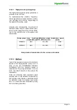
Page 12: ...on pump With an operating pressure of up to 75 bar the water is atomized by means of high pressure nozzles These nozzles generate a very fine spray mist which is taken up by the air in the humidification chamber The ambient air is cooled adiabati cally in the process 4 3 Schematic diagram of the system components 4 29 28 21 27 26 25 24 9 20 22 23 9 Electrical connections 25 Water filter with press...

Page 13: ...lus hysteresis the pumping station switches on the second nozzle section and reduces the pressure to 25 bar Up to an actuator signal of 100 percent the output pressure on the nozzles rises proportionally up to 75 bar and the system reaches the maximum possible humidification output Beyond the switching point the system works in the 2 nd load Hysteresis of the switching threholds is es sential in o...

Page 14: ...reduced again to 25 bar With the control signal now rising up to 100 percent the atomisation pressure rises to 75 bar and the system reaches maximum possible humidification output 4 4 5 Exhaust air cooling The high pressure nozzle system was either ordered as an exhaust cooling system or can be put to exhaust air cooling operation mode by switched wiring when a combined sy stem was ordered s secti...

Page 15: ... unit cabinet the electrical and electro nical components as well as the wiring termi nals are installed below a hinged lid The electronical control unit is responsable for control of the system The touch screen shows relevant operational data and allows for parameter settings The frequency converter produces the waveforms for the asynchronous motor of the pumpsta tion mounted in the lower part of...

Page 16: ...rol manages the system control The touch screen enables the oper ating of the unit and the programming of parameters The display is used for monito ring operating data and parameter settings 2 3 1 4 5 6 8 15 12 11 10 14 7 1 Touchscreen of the electronic control 8 High pressure pump 2 Main switch 10 Wastewate connection 12 mm 3 Electronic control 11 Flushing solenoid 4 Frequency converter 12 Outlet...

Page 17: ... is to ensure the minimum speed of the high pressure pump even in case of very low humidification demand Compliance with the minimum speed is essential for the pump lubrication and as such has direct impact on the pump s life expectancy Units not achieving their expected output capacity due to the limitation intoduced by the by pass valve feature a switched mode for operation under the highest loa...

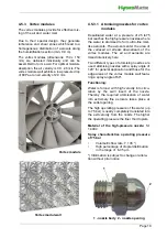
Page 18: ...m of the vortex modules The air and aerosols are mixed intensively here Two different types of atomising nozzles are used atomising nozzles with a spray angle of 120 for general application and those for the edge areas of the vortex module wall featu ring a spray angle of 60 Functioning Water is forced with high velocity into circu lation by the swirl insert of the nozzle Thereby the required atom...

Page 19: ...ions The nozzle system offers a number of flush ing variants in order to cope with the hygienic and maintenance oriented requirements Flushing can be accomplished with supply water pressure only or through use of the vane pump depending on a parameter set ting Also the duration of the flushing func tion may be altered by the setting The following flushing variants are supported Manual flushing Man...

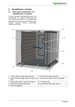
Page 20: ...with the hygienic and safety prere quisites required drains darkenable inspection window 1 2 9 8 7 6 6 5 3 8 7 4 1 vortex module wall with spray system 6 drain with trap free draining 2 upper mounting angle pieces for spray sys tem 7 lower guide rails for aerosol separators 3 upper guide rails for aerosol separators 8 collection tray 4 inspection window darkenable 9 lower guide rail for spry syste...

Page 21: ...ow for free draining The humidification chamber should be aerosol tight and it should be able to withstand desalinated water The minimum humification section length distance between spray system and aerosol separators is 0 9 m This corresponds to a total installation length of 1 5 m see fig 2 in the Instal lation and initial operation instructions for HygroMatik adiabatic humidification systems do...

Page 22: ...ke hoses burst Relative humidity must not exceed 80 r h since values beyond may lead to electronic malfunction or dam age Installation in a closed room requires aeration and eventually temperature conditioning in order to meet the a m environmental conditions Make use of existing water connections for supply and draining The on site waste water connection must be a free outlet according to DIN EN ...

Page 23: ...at the mounted bracket is firmly seated and that it can take the load Insert the sound absorbing buffers 3 into the base holes of the HPS pump station and fasten them Insert the pump station into the wall console and screw it tight Installation steps Floor mounting Mark the holes for the screws of the bracket on the floor Drill and dowel holes Fix mounting rails 1 with the sup plied mounting screw...

Page 24: ...Seite 24 6 3 1 Dimensions and mounting instructions ...

Page 25: ...pes be used We recommend designing the last seg ment of the water pipe to be flexible to prevent translation of vibration from the high pressure pump group to the pipe work All hygienic requirements must be met s section 6 2 1 Supply water quality 7 1 Schematic view WARNING 22 9 11 26 25 30 31 14 32 9 external drain with tap free discharge required 25 water filter intake and outtake with 3 4 exter...

Page 26: ...adapted mounting material 7 2 1 Supply water quality The supply water for the high pressure noz zle system must comply with VDI 6022 i e from a microbiological point of view it must be of drinking water quality A flameresistant sampling tap is to be pro vided on site in the direct vicinity of the HygroMatik high pressure nozzle system Conductivity 5 50 µS cm Pressure 0 1 0 5 MPa 1 5 bar Volume flo...

Page 27: ...ply Was the water filter insert supplied as part of the delivery installed in the water filter housing of the pumpsta tion Is the feed water quality within the prescribed range Water drain Is the drain hose siphoned and installed with a constant decline towards the drain Can the flushing water drain off free ly Humidification chamber Is the humidification chamber provi ded with a drain at the lowe...

Page 28: ...g every 24 hours in order to prevent microbial contami nation in standing water In this situation a momentary increase of humidity in the air conditioning system may happen Thus in order to warrant the drying of the air condition system after flushing the regular operation must be ensured 8 3 Air feed for the nozzle system The air flow must be laminar i e in case of a fan installed upstream of the...

Page 29: ...at all terminal screws are securely fastened Possible electronical components destruc tion through electrostatical discharge Prior to commencing electrical installation work steps e g ESD protection must be tak en to guard the sensitive electronical compo nents of the unit control against damage from electrostatical discharge 9 1 Electrical installation approach Danger of electrical shock due to r...

Page 30: ...tem across terminals 1 and 2 of X1 The contacts across terminals 1 and 2 of X1 must be potential free and suitable for 230 VAC switching After commisioning the high pressure nozzle system a voltage of 230 VAC is present on terminal 1 of ST1 1 on the expansion board wired to terminal 1 of the terminal block X1 If the ventilation system fails or the supply air face velocity is too low less than 0 9 ...

Page 31: ...connections for secure clamping and safe connections Step 2 Switch on the high pressure noz zle system Switch on main breaker Open water supply stop cock Switch on unit by setting control switch to I close safety interlock system Step 3 The unit performs a self test and then commences normal operation During self test the On Off button icon flashes for a couple of seconds On completion of the test...

Page 32: ...ks and correct improper spray image Re work hosing and distribution tube connections if required When nozzles drip check presence and correct seating of o rings When spray image is unsatisfac tory clean nozzles in ultrasonic bath as described in the maintenance section Repeat actions until everything is o k Step 7 All electrical functions must be executable Run through menus and verify sys tem con...

Page 33: ... for the commissioning of one unit During this time the system will be switched on and off for several times and control signals should be allowed to be set manually The presence of an on site control engineer is therefore imperative Please send us the notification of readiness preferably 10 working days before the desired date Best regards Your HygroMatik Service Team We confirm that the above co...

Page 34: ...onal relays in DIN rail format The DIN rail relays are connected via cables with plug Up to 2 additional relay modules can be used with 2 relays each The external circuitry for the control voltage and the interlock safety system wired to the X1 terminal block are fed to the control elec tronics via plug ST1 1 of the expansion board and are looped from there to the mainboard Fusing of the control v...

Page 35: ... plugs ST10 1 and ST10 2 can be used Ex factory relay assignment In case of a unit without any additional options built in assignment of the base relay ST03 is Collective fault All other relay contacs carry the assignment Not in use F1 F2 ST06 ST05 ST04 A ST04 B ST07 ST08 ST03 ST1 ST11 1 ST09 ST10 1 ST10 2 ST13 ST12 1 USB ST15 basic relay connections for optional relays K20 21 K22 23 ordering opti...

Page 36: ... the supply air humidification mode for switching of the 4 th load K21 is freely assignable In units with a switched by pass valve the valve is controlled by relay K21 ST07 Control output for driving the frequency converter 0 10 VDC ST08 03 20 VDC supply max 20 mA USB Connection for USB stick for use as a data logger and for parameter or soft ware updates 11 3 1 2 System side interfaces ST1 4 pin ...

Page 37: ...ff OFF CAN TERM ON CAN TERM OFF ON CAN bus termination The DIP switches serve for CAN bus address setting They are factory preset according to the unit configuration When replacing an ex pansion board ensure the identical setting is made as it was before The jumper for the CAN bus termination is in the ON position only on the lowest pc board of the assembly The termination is then effective On the...

Page 38: ...ST06 0 I plug monitoring 12 VDC 14 fault frequency converter 5 VDC 16 leakage Outputs ST02 A 9 N 3rd load 230 VAC ST03 10 water intake solenoid valve 230 VAC ST04 11 N 1st load 230 VAC only with combined system 11 5 Connection terminals block Power supply 230V 50Hz at X1 FL und X2 FN Potential free contact for release at X1 1 and X1 2 Up to 4 freely programmable relays K20 23 1 step X1 3 5 0 10V X...

Page 39: ...11 6 2 Connection of interlock safety system The so called interlock safety system is located between terminals 1 and 2 of the X1 terminal block Safety equipment can be wired also in series into the interlock safety system If the interlock safety sys tem is open the high pressure nozzle system does not start or the operation is interrupted In air conditioning it is standard to incorpo rate a max h...

Page 40: ...ral terminal block X1 11 6 3 1 Terminal wiring for supply air humidification standard delivery 1 step operation Operation with active humidity sensor or external controller When driving the high pressure nozzle sys tem with an active humidity sensor or through an external controller e g a PLC physical control signals in the range of 0 10 V 0 20 mA or 0 140 Ω can be used For each of the signal vari...

Page 41: ...air humidification exhaust air cooling switch over The parameter Digital_input_function 17 cylinder extension 1 must be set to 50 Switch on of exhaust air cooling Please note 3 4 5 6 7 GND 0 10V Terminal strip on ST08 8 External controller Terminal 4 5 wiring on the mainboard terminal strip on ST08 for connection of a 0 10V external control signal 3 4 5 6 7 GND 8 Terminal 4 6 wiring on mainboard t...

Page 42: ...over 11 6 4 General use of the digital input on the mainboard The digital input on the main board can be used for switching functions unless it has already been configured in ex works The digital input must be wired on site in accord ance with its use e g with a switch also see section 13 Function parameters 20 VDC S1 S2 NO contacts Terminal strip on ST08 Terminal 3 5 8 wiring on the mainboard ter...

Page 43: ...trol_signal_internal Humidity_actual_value_max1 2 Humidity_set_value_max1 2 1 only when PI controller is set 2 only when Floating max limiter is set Screen keyboard for changing the humidity set value is displayed when the humidity set value display is touched allows direct chang ing of the set value Saving of the input by touching the confirmation tick in the upper right corner exit without savin...

Page 44: ...display field dark bright flashes Main contactor switched Main contactor not switched Fault main contactor dark bright flashes Water inlet active Water inlet not active Fault water inlet dark bright flashes Water outlet active Water outlet not active Fault water outlet dark bright flashes Demand has been made Demand has been made Fault demand dark bright Interlock safety system closed Interlock sa...

Page 45: ...e schematically displayed in the table below User guidance In the user guidance a distinction is made between the basic level and advanced level While the basic level only makes it possible to carry out basic device operations the advanced level also permits operating parameters to be changed The 2nd table below clarifies this again The possible oper ating functions of the two levels are pre sente...

Page 46: ... for comprehensive unit settings read values parameter settings service set tings and history 12 7 Screen 4 Unit information Is only displayed after a fault or a service message has occurred provides information on device data statistics faults that have occurred and service requirements 12 9 01 Commissioning Level Permits Basic level Display of the read values of the main screen Setting the humid...

Page 47: ...he Initial operation screen with the green tick in the top right cancel by touching X 13 2 2 Input of date and time The parameter 02 Date and 03 Time require digits to be entered To do so a screen with a keyboard and an input field in the date or time format will be displayed after touching the relevant line As an example the date input is described below Touch line 02 Date The following screen is...

Page 48: ...a maximum of 4 entries Scroll keys are used to switch between the individual screen blocks Confirm the input and return to the Initial operation screen with the green tick in the top right cancel by touching X Pressing the green tick in the top right saves the entries and exits the initial operation screen cancel by pressing the X The initial operation is now complete If the initial operation scre...

Page 49: ...A 3 External controller 73 with ohmic signal 0 140 Ω 4 Internal PI controller 96 controls with voltage signal 0 10 V 5 Internal PI controller 96 controls with current signal 4 20 mA 6 Internal PI controller 96 controls with ohmic signal 0 140 Ω 7 1 step operation 44 8 Control via software control commands 12 through communication interface 13 11 Selection of current input on the mainboard for the ...

Page 50: ...ain screen see Section 11 The screen With the exception of the target humidity these are read values only The displayed values are shown and explained in the table in the following section If an error has occurred or a service message is issued a display field with the relevant message is displayed instead of the Hygro Matik logo The user can access the unit info screen by touching this field The ...

Page 51: ...on of the term Pressure_acutal_value The current system pressure in the unit in bar Pressure_set_value The set point of the system pressure in bar Frequency_set_value The frequency set value for the frequency inverter Load_actual The current load range of the system at the time of reading Humidity_actual_value Actual value 1 of rel humidity 2 in Humidity_set_value 0 0 99 0 50 0 Set value 3 of RH 2...

Page 52: ...hown on the screen for entering the password To open the basic level it is sufficient to select the X symbol top left The advanced level is accessed through the sequential input of the code digits 0 1 and 0 and confirming them with the green tick top right 13 5 Screen 3 Main menu basic level After selecting the basic level the icons of the submenus which are available without password entry are di...

Page 53: ...ng the screen brightness Touch Screen_brightness normal on the screen to call up the input mask The screen brightness which is set is dis played and can be changed by using the key board Save and return by touching the green tick leave the input mask without changes by touching the X The screens are hidden after a certain period of time The main screen is then displayed The time until the return t...

Page 54: ...ertain screen page before return to the main screen in min 6 Display_lighting_dimmed 0 100 50 Screen brightness for dimmed state 7 Display_dim_after 0 3600 120 Switching of screen brightness of main screen to dimmed value after seconds If an error has occurred or a status message is displayed the main screen is not dimmed 8 Units Selection of system of units 0 Units are displayed in the format of ...

Page 55: ...ble unit fault messages 7 Service_message_unit Service message unit 17 Demand The demand 5 is the control signal from which the internal actuator signal 42 is created 18 Control_sig _internal Internal actuator signal 42 as a percentage of the actuator signal for the nominal output 20 Safety_interlock Status of the interlock Safety system 11 0 The interlock safety system is open 1 The interlock saf...

Page 56: ...1 Flushing of the cooling nozzle section is in progress only for combined systems 32 A hygiene flush is underway 33 The flushing of the humidification lines and the cooling line is in progress only for combination systems 99 The switching points for load changeover are not set correctly 62 Solenoid_valve_flush Status of the flushing solenoid valve 0 closed 1 open 63 Solenoid_valve_inlet Inlet sole...

Page 57: ...ult_message_unit 3 1st fault_entry_rate 1 Memory entry Frequency of occurrence since initial operation 4 1st fault entry 1st memory entry source of occurrence 0 is not known 1 is the motherboard 4 is the humidifier 20 is the expansion board 1 5 2nd fault_entry_date 2 Memory entry Date time 6 2nd fault_entry_message 2 Memory entry Error message see above 7 2nd fault_entry_rate 2 Memory entry Freque...

Page 58: ...y of occurrence since initial operation 32 8th fault entry 8th memory entry source of occurrence 33 9th fault_entry_date 9 Memory entry Date time 34 9th fault_entry_message 9 Memory entry Error message see above 35 9th fault_entry_rate 9 Memory entry Frequency of occurrence since initial operation 36 9th fault entry 9th memory entry source of occurrence 37 10th fault_entry_date 10 Memory entry Dat...

Page 59: ...f the respective group are available for selection viewing or for making changes The layout of the screen pages corresponds to the pages of the submenus of the basic level see Section 13 6 Naming of the submenu follows internal reasons only there is no cylinder built into this device The submenu serves for the parameterisation of the expansion board that is attached to the mainboard and is used fo...

Page 60: ...0 100 Screen backlight in undimmed state 5 Delay_present_page 0 3600 300 Display duration for a certain screen page before return to the main screen in min 6 Display_lighting_dimmed 0 100 50 Screen brightness for dimmed state 7 Display_dim_after 0 3600 120 Switching of screen brightness of main screen to dimmed value after seconds If an error has occurred or a status message is displayed the main ...

Page 61: ... 17 Humidity_set_value 0 0 99 0 50 0 Set value 3 of RH 2 in 20 PI controller_gain 0 5 100 0 5 0 Proportional part of PI controller 21 PI controller_integral 0 100 10 Integral part of PI controller 22 Humidity_notification 5 0 99 0 50 0 When the set humidity has been reached one of the relays is energised which must have been assigned code 211 humidity reached for this purpose 23 Humidity_set_max 5...

Page 62: ...ervice message is displayed The main contactor must then be changed and the message has to be reset by setting the Main_contactor K1_Reset parameter 06 Service 12 Table of service parameters 06 Service No Parameter No Meaning Comment explains the term in the glossary Min Max FS refers to a related explanation of the term 3 Operating_time_service 0 5000 2500 Preset operating hours see 37 until serv...

Page 63: ...pdate process is displayed see table Its successful completion is dis played by the Update successful status message Switch the unit off and on again The loaded parameter set is activated To reload the parameter set at a later date if required e g after a fac tory reset the ImportDone txt file on your USB stick must be deleted beforehand To do so the stick must be inserted in an external device e ...

Page 64: ... 74 is to be generated following humidification S 12 the device has completed initialization and is not in error M 13 20 the digital input of the motherboard is activated M 38 the minimum water inlet pressure is not reached 68 An additionally installed relay is to be actuated which switches the input solenoid valve for flushing the dead leg line if the interlock safety system is not closed S 150 L...

Page 65: ...the communication interface 13 2 Baud_rate Setting the baud rate 3 9600 4 19200 6 38400 3 Parity Parity setting 0 Without parity bit 1 Odd parity bit 2 Even parity bit 4 Stop_bits Number of stop bits 0 1 stop bit 1 2 stop bits 5 Modbus_timeout 0 60 20 Timeout in s for software control commands 12 through communication interface 13 6 BACnet_MacID 1 127 1 Physical address of a BACnet device within t...

Page 66: ...e duration of the flushing time in seconds with pump pressure or line pressure according to the setting made beforehand 5 Relieve_Duration 1 240 5 Determines the duration of the pressure relief 85 in seconds 6 Delay_reverse osmosis system 10 180 10 Delay between opening the inlet solenoid valve and starting the high pressure pump Enables the pressure build up in the reverse osmosis system 7 Load_s...

Page 67: ...w Set parameter Saving_start 16 Recording 2 to 1 on Saving starts automatically Then parame ter Saving_start returns to the 0 state Off By looking at parameter Saving_status 16 Recording 4 the status of the saving procedure can be checked 1 Activated means that writing to the memory stick is underway Erasing of the complete memory is achieved by setting the Recording_delete parameter 16 Recording ...

Page 68: ...ocess 0 Saving not possible 1 Saving is enabled 5 Recording_delete Delete recording 0 No action 1 Delete recording Adjustment value range Factory setting FS Bold Selection Off On Read value Deactivated Activated Selection Deactivated Activated Selection Off On Selection Off On ST04 ST03 ST02 A ST04 B Table of the parameters for the expansion board 17 Cylinder_extension No Parameter No Meaning Comm...

Page 69: ...ction 14 Touching this display field calls up the unit info screen which extends over several screen pages and contains comprehensive device data As an example one possible first screen page is shown here The content of the screen pages is provided in the table in the next section Pressure_actual_Value bar Fault 001 02 Information 01 Error message_unit 04 Service message_unit 08 Unit name 07 Unit ...

Page 70: ...s not fallen below the minimum value for a contigous period of 10 minutes 16 The nozzle condition of the spraying system requires maintenance 18 The control of the humidifier should be optimized 19 The actual pressure falls below the target pressure by 1bar for at least 180s at one frequency of 50Hz Cause slight leaks in the Area of nozzles and tubing as well Pump wear This service notification so...

Page 71: ... Code Fault message Possible cause Counter measure 002 Expansion board Expansion board not detec ted by the sofware p c b connection not o k Check firm connec tion of boards p c b not present or defective Connect board replace board if defec tive CAN bus addressing not correct Check DIP switch settings on extension board see fig in sec tion 3 4 022 Input_current_min The min value of the input sign...

Page 72: ...perly set Please contact HygroMatik 152 Min pressure Pressure cannot be built up within 90 seconds after actuation of the high pressure pump Pressure hose leaky Check pressure hose and replace if required Overpressure protec tion on high pressure pump not properly set Please contact HygroMatik Pressure variations in RO device Check RO device 153 Water inlet pressure Water inlet pressure is below 1...

Page 73: ... temperature above 50 C 10 Air inlets and outlets clogged Remove blockage s 158 Pump temperature Thermoswitch on high pres sure pump has tripped after temperature exceeded 60 C Nozzles or hoses blocked by e g debris Clean nozzles and or pressure hoses Incorrectly set by pass Check and set the by pass valve to 9 Hz at a 1 V control signal Ventilation of the housing not existent Check housing venti ...

Page 74: ...arame ter 15 14 The appearance of the service message increments an internal counter Whenever this counter shows 5 entries the fault message water inlet pressure 02 1 no 153 is generated The internal counter is decremented each time when the water inlet pressure has not undercut its specified mini mum for 10 mins without interruption Service_Nozzles The spray system noz zles are not working at the...

Page 75: ...ting spray cone of the nozzles and clean nozzles if necessary also see section Clean ing the high pressure nozzles 1 x per year or after 2500 h Check the nozzles as part of annual maintenance and clean in an ultra sonic bath also see section Clean ing the high pressure nozzles Replace nozzles if required Change the high pressure pump oil Change sealings and valves of the high pressure pump Replace...

Page 76: ...ing Tighten the drain screw 2 with the sealing ring in place Risk of material damage to the high pres sure pump caused by inadequate oil fill ing Only use mineral oil Add 15W40 motor oil approx 0 4 l via the filler hole 1 Check the oil level using the dipstick and close the filler hole The unit is now ready for restart by pushing the control switch to the I position 1 Oil filler hole with dipstick...

Page 77: ...f pliers are used Clean the filter housing Replace the filter cartridge if neces sary Screw the filter housing into the seat by hand Do not pinch the sealing ring Open the supply water stopcock The unit is now ready for restart by pushing the control switch to the I position 15 1 3 Flushing the mains water sys tem Set the control switch on the control cabinet of the high pressure nozzle system to ...

Page 78: ...or restart by pushing the control switch to the I position 15 1 5 Cleaning the aerosol separa tors The aerosol separators should be checked every 4 weeks for possible contamination and cleaned if necessary The aerosol sep arators should be thoroughly cleaned at least once a year Set the control switch on the control cabinet of the high pressure nozzle system to 0 Pull or lift the aerosol separator...

Page 79: ...erosol separators should be reviewed as a part of the annual mainte nance for contamination or damage Possible impurities must be removed with a cleaning agent 15 1 8 Cleaning the humidification chamber Clean the humidification chamber and the base tray as required with the cleaning agent that is recom mended by the manufacturer of the humidification chamber After cleaning rinse and let dry Risk o...

Page 80: ...rews 3 2 screws are hidden in fig of the cou pling bell and separate the coupling bell with the pump from the motor pull in the direction of the arrow in the fig Place the high pressure pump with the coupling bell on a suitable sur face Rotate pump shaft 9 until the later ally attached securing screw 8 is visible through the slot 5 of the bell shaped top Loosen screw 8 and pull thecou pling piece ...

Page 81: ...y the sealing ring from the shaft Reassembly Position new sealing ring on the shaft by rotating movements and press ist evenly in its seat Perform the rest of the steps for assemby in reverse order of the dimantling Remount oil drain screw 2 paying attention to the sealing ring Fill the pump with suitable mineral oil of the specification 15W 40 through the filler hole 1 until the sight glass 12 is...

Page 82: ...ith a smal screw driver or sim ilar For reassembling lay the new O ring 15 in the valve seat Put the valve into the holder Screw the holder with the valve into the pump 15 2 3 Replacing the seals on the water side If water leaks occur on the pump the seals must be replaced In order to do this the water supply must be turned off the system must be switched off at the main switch and the water conne...

Page 83: ... be used 15 2 4 Calibration work after repair or replacement of the high pres sure pumpstation 15 2 4 1 Setting of the overpressure protection Overpressure protection setting is restricted to a basic setting for the unit operator Method Switch off unit making use of the control switch Turn overpressure protection rotary handle 20 counterclockwise until it almost comes off Screw in headless Allan s...

Page 84: ...Unfasten headless Allan screw 2 on by pass valve 3 and adjust valve slowly until a frequency between 9 and 12 Hz can be read in the frequency converter display Fasten Allan screw again for secur ing the setting Return to the normal operation set tings should they have been changed 3 1 2 5 1 Distribution manifold 2 Headless Allan screw 3 By pass valve 4 Solenoid valves for pressure hoses 5 Rinse va...

Page 85: ...Seite 85 16 Declaration of Conformity ...

Page 86: ...plete inkl mountig set x x E 7701000 Vortex module x x E 7700558 Adjustable stud barrel tees EL VD 06 L stainless steel x x B 7800311 Spraying nozzle HY 0 27 120 incl O Ring LPS HDS HPS x x B 7800313 Spraying nozzle HY 0 27 60 incl O Ring LPS HDS HPS x x E 7601572 O ring 70 Shore EPDM for vakuum valve VV8 and for HDS LPS Nozzle x x B 7771053 HDS nozzle holder complete with o rings and connector fo...

Page 87: ...re parts you find a template on the www hygromatik com website under the Contact tab Your spare parts order can also be sent directly per e mail to hy hygromatik de Please make sure to specify your unit model and serial number ...

Page 88: ...f nozzles 6 39 18 104 Humidification section length ideally m Total installation length ideally m Air velocity m s Pressure loss in duct Pa Pump station height mm Pump station width mm Pump station depth mm water conection High pressure nozzle system HPS 0 10 0 20 0 140 230 1 N 50 60 0 9 1 5 0 9 2 8 80 2 0 m s 1 other control signals on request 734 782 399 demineralised water remaining conductivit...

Page 89: ...minal 1 carrying 230 VAC as standard In a special design e g for the U S market the interlock safety system is converted to low voltage through the additional use of a relay K21 to meet local safety requirements Instead of terminals 1 and 2 on the control a potential free connection of the relevant DIN rail terminals must then be implemented on site If the interlock safety system is opened the sta...

Page 90: ...between terminals 3 and 5 of the control Humidification 47 The unit humidifies if a Hygrostat 6 an External control 73 a Humidity sensor or a Software control command 12 has issued a Demand 5 and the Interlock safety system 11 is closed Correction_x_signal 49 Used for the calibration of a humidity sensor output signal as the Input signal 72 of the control x V mA Ω Exhaust air cooling 62 Operationa...

Page 91: ...pplying an Auxilliary voltage 105 either short term via a push button or permanent via a switch Load shedding 101 Load shedding can be set up by assigning the Function_digital_input 98 Power limitation to the Digital input 97 When the Digital input 97 is then then connected to an Auxilliary voltage 105 by means of a Switch NO 102 Max humidification output 43 is reduced by the percentage set up in ...

Page 92: ...Ein Unternehmen der Gruppe 100 Lise Meitner Str 3 D 24558 Henstedt Ulzburg Telefon 04193 895 0 Fax 33 eMail hy hygromatik de www hygromatik com Ein Mitglied der CAREL Gruppe ...

Reviews: